
Q: How can I take a HART Primary Variable (PV) from an oxygen transmitter (with only one HART output available), and output two identical analog signals?
A: Here are two approaches you can use by utilizing Moore Industries SST HART Functional Safety Isolator and Splitter or the HIM HART Loop Interface and Monitor.
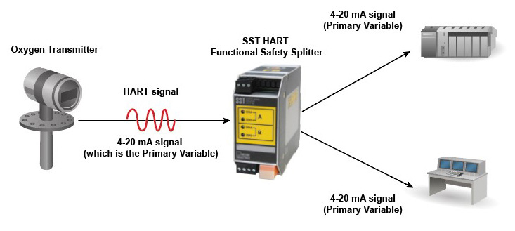
SST Splitter Solution:
Since the oxygen transmitter has a HART output, we know that this particular output is a 4-20mA signal plus the HART digital signal. We also know that the 4-20mA signal is the HART Primary Variable. Therefore you can wire your oxygen transmitter to the SST Splitter to split the 4-20mA signal and send it to your two destinations as a 4-20mA signal. This is the less expensive approach. The SST solution could also send the HART digital signal to both destinations, if that had value to the user.
HIM Solution:
Since the O2 transmitter HART output digital signal also contains the Primary Variable, you can wire your oxygen transmitter to the input of the HIM. The HIM will read all the HART Dynamic Variables, but we will assign the Primary Variable to two HIM 4-20mA outputs which go to the two destinations. The HART digital signal does not get passed to the HIM analog outputs.
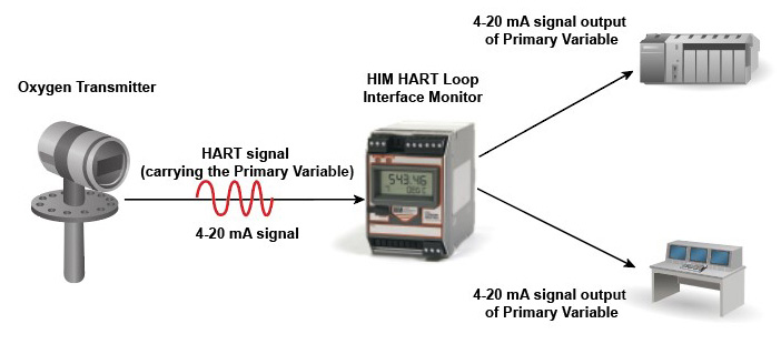
While this is the more expensive strategy, it does offer significantly more flexibility in your system. The HIM can send up to three analog output signals, as opposed to just splitting an analog signal in two; these analog signals can all be the same Primary Variable, or they could be the Second, Third, or Fourth Variables, which are also contained within your oxygen transmitter’s HART output signal. In addition, the HIM can provide you with two relays for Process or Diagnostic alarming and has a large 5-digit display for ease of use. Because the HIM is a configurable device it can easily be repurposed in the future.
Do you want more information? Download the data sheet. Or visit the catalog.
Need to get price or availability or have a technical question?
Send us a message using E-Help.
Q. What is the purpose of increasing input resistance to 250 ohms with the IZ250 option on the Moore Industries SSX signal isolator/repeater?  A. If you anticipate that the total loop resistance where your HART transmitter resides will be lower than 230 Ohms, this option will ensure you have enough impedance in the loop to create a sufficient voltage drop for reading the HART signal by a HART host (handheld or input card). The HART digital specification requires the loop to have total loop impedance between 230 and 1100 Ohms in order to initiate and maintain stable communication with HART devices.
Do you want more information? Download the data sheet. Or visit the catalog.
Need to get price or availability or have a technical question?
Send us a message using E-Help.
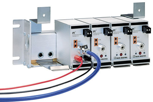 Q: A field tech told me he installed an IPT2/4-20MA/3-15PSIG/20PSIG/-FA1 [DIN] unit. In the product bulletin, I don't see a purpose for the trailing "2" in the model name, and I don't see an explanation for -FA1.
A: The “2” in IPT2 indicates that it is the successor to the older IPT. It is a direct replacement with the same form/fit/function with improved performance. This next-generation IPT2 I/P Transmitter provides advanced features including 18 standard pressure output ranges, lower air consumption, quick response to step changes, greater accuracy, drift reduction, and more.
The -FA1 option provides a mounting block for the installation of the unit on DIN rail. It also designates that the supply and outlet ports are on the bottom of the mounting block, the electrical signal test jacks, and electrical connections are on the front face and that there is no pneumatic test jack. (see table 2 on page 3 of the data sheet for the explanation.)
Do you want more information? Visit the catalog.
Need to get price or availability or have a technical question?
Send us a message using E-Help.
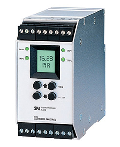 Q: We are considering ordering the Moore Industries SPA/0-100mV/2 PRG/U/-SOL [DIN]. Can we power it using 24VDC? If so, what is the power consumption and how do we terminate? Also, can you please confirm whether this unit is Class 1 Div2, group A,B,C,D?
A: The SPA can be powered with 24VDC. It accepts any source voltage in the ranges of 22-300Vdc or 90-260Vac. Power Consumption is 2-4W, nominal; 6W, maximum.
If you specify the -HS option (hermetically sealed relays) then it is approved for Class 1 Division 2 locations when installed in an enclosure that provides sufficient mechanical and environmental protection. Usually, a NEMA 4 rated box will serve. See page 1 of the data sheet (click the link to open the download page).
The sample model number with -HS option and with a NEMA 4 enclosure is:
SPA/0-120MV/2PRG/U/-SOL-HS [R3H].
The –SOL option in this model number indicates a specially engineered SPA used to monitor the health of solenoid valve coils.
Do you want more information? Download the data sheet. Or visit the catalog.
Need to get price or availability or have a technical question?
Send us a message using E-Help.
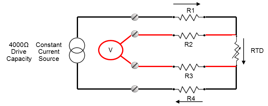
Q: What are some ways to improve the long-term stability of my RTD temperature measurement?
A: There's no question that the first step in improving the overall quality and long-term stability of your temperature readouts is to use a Class A, 4-wire RTD. Lead wire imbalances are a major cause of instability during the measurement process. A single ohm of imbalance in a three wire, platinum .00385 alpha, 100 ohm RTD can produce as much as 2.5°C of error in a measurement. By adding a fourth lead wire, you eliminate potential errors in measurements created by resistance imbalances between leads. 4-wire RTDs are no longer just for special uses, and they aren't cost-prohibitive. In fact, in many cases they are more cost-effective than using traditional 3-wire RTDs.
Another way to improve long-term stability is to make sure that your RTDs have been thermally aged. This process involves placing RTDs into a continual cycle of temperature extremes that season the RTD and even help extend its measurement life. The sensors that we use in high-accuracy applications have been temperature cycled from 0°C to 600°C for 1,000 hours, making them virtually drift-free for the next five to 10 years.
Do you want more information? Find a data sheet here. Or see our Temperature Transmitters or Temperature Assemblies and Sensors.
Need to get price or availability or have a technical question?
Send us a message using E-Help.
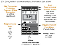 Q: For the STA 4-Wire SIL 2 and SIL 3 Compliant Programmable Current/Voltage and RTD/Thermocouple Safety Trip Alarms, can the process alarm relays be configured as Failsafe? Can the process relay output of the SPA2-TRPRG be configured Failsafe?
A: The output relays of the STA are configured only as Failsafe. For example, the coils are de-energized in the alarm condition or when there is a loss in power. For systematic integrity up to SIL 3 and for random integrity up to SIL 2, the STA is also exida certified 61508:2010. This means that an STA is approved for single use in Safety Instrumented Systems (SIS) up to SIL 2 and in redundant architectures (1oo2, 2oo3, etc.) up to SIL 3.
The output relays of other alarms that we offer such as the SPA2 can be configured either as Failsafe or Non-Failsafe.
Download the SPA2 or STA data sheet for more details.
 Q: Does your SPA2 have a SIL 2 rating?
A: The SPA2 can be used in safety instrumented systems (SIS) as long as the appropriate safety-related data and restrictions in use are reviewed and followed by a competent safety practitioner. We have a FMEDA (Failure Modes, Effects and Diagnostics Analysis) report that provides this data for the SPA2, and is available upon request.
We also offer the STA Functional Safety Limit Alarm Trip, which is expressly designed for safety related applications and has third party certification (exida) per IEC 61508:2010 for systematic integrity up to SIL 3 and for random integrity up to SIL 2.
The exida certified FMEDA data can be provided and used by a competent functional safety practitioner to calculate the required PFDavg and determine the SPA2s or STAs SIL capability and overall suitability in your Safety Instrumented Systems (SIS).
Do you want more information? Download the data sheet. Or visit the catalog.
Need to get price or availability or have a technical question?
Send us a message using E-Help.
 Q: I am looking for a signal conditioner that has multiple inputs (RTD) that can be averaged on one mA output. What do you recommend?
A: First determine how many RTDs you need to average, the number of wires (2-wire, 3-wire, or 4-wire), and are the cable lengths the same for each RTD? Then we can help you determine which product will fulfill your specific needs.
Moore Industries has several products that can handle multiple RTD inputs and provide a calculated average output.
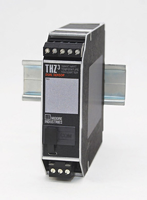
Both field-mount and Din-mount models are offered. The THZ3/TDZ3 models handle two RTD inputs while the SPT, MDS and NCS handle three or more RTD inputs. If you have an application that involves Safety Instrumented Systems (SIS), the STZ transmitter family can be used.
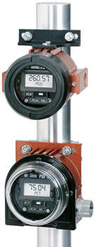
The THZ3 is a smart HART two-wire, output loop powered transmitter that comes in a hockey puck configuration for field mount applications or in a DIN rail mount package for cabinet installations. The TDZ3 is a field mount unit with an integral display. Both units offer the ability to output a 4-20mA signal that represents the average of the RTD inputs.
 The SPT accepts T/C, RTD, millivolt, or ohms input in different ranges, sensor types, and connection schemes. The SPT has a simple menu system and LCD screen for easy setup and calibration, and all settings are stored in non-volatile memory, protecting them from power loss.
The I/O Equation Station Multifunction Distributed I/O System (MDS) is a four-wire module that can average up to 4 RTDs. The number of wires per RTD depends on the number of RTDs that can be connected.
The Net Concentrator System (NCS) is an expandable I/O system that consists of input and output modules that can be configured to accept any number of RTD inputs to calculate an average output. The NCS can be programmed to handle a wide range of signal input and output including current, voltage, discreet, relay, RTD, thermocouple, resistance, and potentiometer with an operating range of -40°C to +85°C.
Do you want more information? Download the data sheet. Or visit the catalog.
Need to get price or availability or have a technical question?
Send us a message using E-Help.
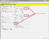 Q: We do not have sufficient PLC digital output spares to perform a Manual Reset of the three installed safety temperature controllers. We are going to remove the alarm latching on both limits and faults on our STA Functional Safety Alarm Trip. The Manual Reset radio button stays active in the STA configuration software. Will the latches clear after we are outside the dead band limits?
A: The radio buttons selected in the Manual Reset rectangle are irrelevant if you have not checked any of the Latching check boxes in the Display Alarms tab. Therefore, if latching is unchecked, the alarm state will reset once normal conditions exist after a brief event.
When using the configuration software, settings are downloaded to the instrument in the form of a Configuration File and stored in the instrument’s memory. You can save a backup copy of the file on your PC hard drive. The STA communicates with the PC through an RS-232 connection to the PC’s serial port or optional USB Communications Cable. Learn more about the STA Functional Safety Alarm Trip.
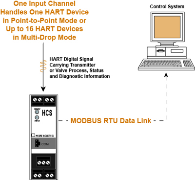
 Q. What are the advantages and limitations of HART protocol or an instrument with MODBUS communication embedded? How many instruments can the HCS interface in the same loop? Are we able to read/write the five instruments at the same time using HART?
A. Today, a major advantage that HART and MODBUS RTU possess is industry- wide acceptance by users and manufacturers. HART-enabled transmitters, valve positioners, flowmeters, and other smart devices superimpose a digital signal upon their 4-20mA process signal. Combining digital communications with the 4-20mA DC signal provides flexibility of application for process control instrumentation and accommodates multiple variables and device self-diagnostics. HART field transmitters measure process parameters as well as generating a 4-20mA signal used for process control by a DCS, PLC or some other control system and are easily configurable or diagnosed with a HART handheld communicator (HHC). Several digital control system vendors offer a HART based systems for predictive maintenance that take advantage of the HART devices’ self-diagnostic capability. The disadvantage to HART is that the digital signal is slow. A maximum of 16 HART devices can be connected on a HART multi-drop loop. In that case, the analog signal is fixed to a value of 4mA.
The advantages of MODBUS RTU are that it is strictly digital (RS485) and it’s relatively fast but it does require at least two wires for signal and two wires for power; unlike HART that has signal and power over the same two wires. A significant number of MODBUS RTU addresses can be connected in multi-drop on the signal RS485 data link.
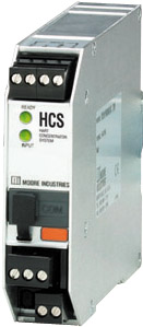
The HART Concentrator System HART-to-MODBUS RTU Converter (4-Wire) HCS is a HART Master (either the primary of the secondary master), and sends queries to the HART device(s). The HCS can communicate with up to 16 devices in multi-drop mode on one twisted pair loop. The collected data is stored in MODBUS RTU registers in the HCS. On the MODBUS side, the HCS is a MODBUS RTU Slave, so it responds to queries from a MODBUS RTU Master. The MODBUS RTU Master can only read data from the HCS. It cannot write data to the HCS with the intent to change settings in the HART device(s).
In a HART multi-drop loop, each instrument will have its own unique HART address. HART does not allow simultaneous communication to multiple instruments in a multi-drop loop. Instead a HART master or host has to poll each HART slave’s unique address and communicates with one HART device at a time. Moore Industries’ HCS HART Concentrator System converts a HART digital signal to a serial (RS-485 or RS-232) MODBUS RTU communication protocol. This allows HART transmitters and valves to interface directly with MODBUS-based monitoring and control systems. In point-to-point HART mode, the HCS concentrator system is set to monitor a single instrument. Wiring details for both single loop and multi-drop are shown in the HCS. In a multi-drop, the HCS sends queries and receives data from each HART instrument in turn. This follows the defined HART protocol.
Do you want more information? Download the data sheet. Or visit the catalog.
Need to get price or availability or have a technical question?
Send us a message using E-Help.
 One of our customers uses ethylene for its process feed and has installed a new ethylene terminal with a 18m3 storage tank. It was necessary to install a new pipeline network to connect the terminal to production plants, other existing pipelines, and to neighboring companies using ethylene. For safety reasons, the pipeline was buried 1.5 meters deep.
To monitor temperatures across the pipeline, 16 temperature sensors needed to be installed at various points. Because the integrity of the pipeline was critical for safety reasons, there could be no welding or other intrusions into the pipe. This led to using skin sensors that meet ATEX Explosion-Proof requirements to take the temperature measurements.
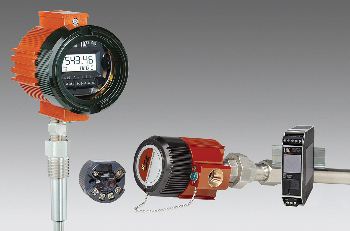
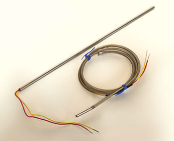
A typical solution is a 6mm-diameter mineral-insulated RTD or T/C sensor with a skin path that is strapped to the underground pipe while a cable travels to the surface where the head is installed. The problem with this design is if the sensor fails, it requires expensive digging near the underground pipeline to replace. A better solution uses a pipe skin mounting block strapped onto the buried pipe, a 1/2"-diameter stainless steel pipe that reaches the surface and a transmitter directly mounted onto the pipe. This allows a sensor to be replaced without costly digging but also means that a sensor needs a sensitive tip.
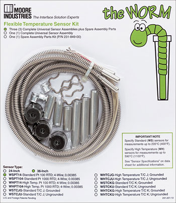
A perfect choice for this application is the WORM Flexible Sensors for Thermowell Temperature Assemblies. It provides accurate, fast readings and its flexible design with a universal length allows it to reach almost any spot. The WORM’s unique flexible design allows installation quickly and it delivers step response times 13% faster than standard sensors. The installation kit provides parts for three different installation options. The WORM can be purchased in economical 10 packs. Check out the WORM data sheet for more details.
Want to learn more? Get the product data sheets on other products such as THZ3 & TDZ3 Dual Input Smart HART Temperature Transmitter, THZ DH & WL Smart HART and WirelessHART Temperature Transmitter (2-Wire), and BULLET WirelessHART Adapter.
Do you want more information? Download the data sheet. Or visit the catalog.
Need to get price or availability or have a technical question?
Send us a message using E-Help.
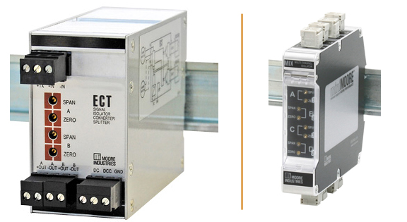
 Q. I have an application that requires an analog splitter. The single input signal to the splitter comes from a transducer, and the transducer requires loop power. The two outputs are going to an analog monitoring card on a PLC, which provides power to the connected 4-20mA signal signals. Is the ECT what I need?
A. If you need a device with two outputs and with output loop power, the MIX would be a good choice. However, this model does not provide loop voltage to the input. It is a dual channel isolator so you would connect the input signal in series to the two input channels. MIX 2 and 4-channel models draw operating power from the loop output side, where power is typically made available by the receiving device, such as a DCS or PLC.
The ECT “Splitter” on the other hand provides loop voltage to the transducer, and it also provides the voltage to the two output loops. It requires a power source separate from the output signals.
You can specify either 24DC or 117AC for the separate power input. If the outputs must be compatible with a control system input card that is providing loop voltage then the EP option for the ECT modifies them to be passive. However, a separate power source is still required. The ECT offers Superior signal isolation (up to 1500Vrms). An ECT with the following model number would meet your application requirements: ECT/4-20MA/4-20MA/24VDC/-EP [DIN]
Quality and industrial strength protection stops ground loops, motor noise, and other electrical interference from affecting process signals. The ECT offers RFI/EMI protection against the unpredictable, harmful effects of radio frequency and electromagnetic interference. There is even a –RF option for enhanced protection in especially noisy environments.
Please visit our Interface Solution Download Center for more information on the MIX or the ECT line of products.
Do you want more information? Download the data sheet. Or visit the catalog.
Need to get price or availability or have a technical question?
Send us a message using E-Help.
 Q. I want to split out the HART variables from a smart multi-variable transmitter's 4-20mA analog output. My preference is to have the secondary variable (SV) and tertiary variable (TV) represented as additional 4-20mA outputs so I can connect those to spare analog input channels in my DCS. Can the HIM do that?
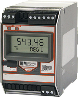
A. Yes, it can. The HIM is a Smart HART® Loop Interface and Monitor can be configured to act as a Primary or Secondary Master and can read up to 4 of the dynamic variables of a HART transmitter and can assign them to up to three analog 4-20mA outputs with no additional process penetrations or wiring. A free simple-to-use PC program lets you program the HIM in minutes so that it interfaces with every HART-compatible monitoring and control device including:
- Multivariable Mass Flow Transmitters
- Coriolis, Magnetic, Ultrasonic and Vortex Flow Meters
- Dual-Sensor Temperature Transmitters
- pH Transmitters
- Pressure Transmitters
- Radar and Hydrostatic Level Transmitters
- Valve Positioners and Damper Operators
When configured as a Primary or Secondary Master, the HIM operates in the Normal(Poll/Response) Mode. Additionally the HIM can be configured to communicate in Burst Mode or Listen Mode; which are both passive modes where the HIM does not need to control poll the HART slave transmitters.
Installed transparently across the 4-20mA instrument loop, the HIM reads the HART digital data that is continuously being transmitted on a smart transmitter’s analog loop wires, and converts it to 4-20mA signals that can be readily accepted by a DCS or PLC. This allows you to continuously track a multivariable transmitter’s second, third, and fourth variables.
In the future if you want to just isolate or split off a HART/4-20mA signal, then Moore Industries offers isolators, which can pass the digital HART component variable of the signal. Isolator models Moore Industries manufactures are the HIX, HIT, SSX, and SST.
Find out more about the HIM Smart Hart® Loop Interface and Monitor.
Do you want more information? Download the data sheet. Or visit the catalog.
Need to get price or availability or have a technical question?
Send us a message using E-Help.
Q. Can the ECT-DIN, configured for 4-20mA input and 4-20mA output, be calibrated to give 4-12mA output when the input is 4-20mA so that the output is 1/2 the input? We have a radio I/O signal that is scaled to 4-20mA for 0-65,535 raw units. When sent to the PLC over MODBUS, it can't be read properly since the maximum register value size for the PLC is limited to 32,767.
A. The ECT with 4-20mA input/output doesn’t have enough adjustability to do a split range like the one you describe. Although it is possible for us to supply a special version of the ECT with 4-12mA or 12-20mA output, or you can use a PC configurable unit such as the CPT/HLPRG/0-20MA/117AC [DIN].
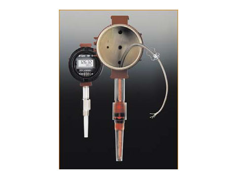
The universal CPT PC-Programmable Temperature Transmitter and Signal Isolator/Converter accepts a direct signal input from a wide array of sensors and analog devices including 23 RTD types, 9 thermocouple types, current and voltage signals, resistance and potentiometer devices, as well as direct millivolt sources. The 4-wire (line/mains-powered) CPT provides an isolated and linear current or voltage output (any range within 0-20mA or 0-10V) proportional to the input. The signal is ready for direct interface with readout instruments, recorders, PLC, DCS, or PC-based SCADA systems.
The CPT data sheet, manual, and configuration software can be downloaded from our site.
Do you want more information? Download the data sheet. Or visit the catalog.
Need to get price or availability or have a technical question?
Send us a message using E-Help.
 Q. We want to use a SPD Field-Mount Programmable Loop Display with a radar transmitter mounted on the top of a cone-shaped bottom tank that outputs 4-20mA signal, and we would like to know how to account for the linearization function representing the volume measurement in the tank at various levels?
A. There are several things you can do depending on what information you have regarding your tank. Some tanks come with a strapping chart and the chart will tell you what volume you have at different levels inside the tank.
In this case, you can load a list of ordered pairs in a CSV (comma separated value) format into the SPD. Alternatively the SPD configuration software allows you to import a CSV (comma separated value) file that represents your linearization table, from Microsoft Excel for example. The SPD allows for custom curves using up to 128 linearization points.
If you do not have a strapping chart, you will need to do some math to relate the level in the tank to the tank volume based on the geometric shape(s). For example, at 5 inches you may have 5 gallons, and at 8.5 inches, you might have 10 gallons. If you have a vertical cylinder on top of a cone, the calculations should be relatively easy. A more difficult calculation would be a horizontal cylinder with F&D (flanged & dished) heads and with various nozzles.
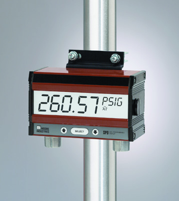
The SPD is an excellent choice as a programmable field-mount loop indicator with extra-large 5-digit display that has large 29mm (1.15 in) digits for long-distance viewing and can be ordered with a back-lit option. The optional back-lit display makes it easy to read in dark conditions. Superior accuracy allows the SPD to display process information ±0.012% of input scale, it can operate in ambient conditions as low as -40°F, and a standard SPD is loop-powered by less than 2.3 volts (2.3VLP power input module). The SPD is also programmable with supplied configuration software to display a percent or any other engineering unit (EGU) of up to 5 characters.
Do you want more information? Download the data sheet. Or visit the catalog.
Need to get price or availability or have a technical question?
Send us a message using E-Help.
Q. What is the maximum impedance that the output of an output loop powered ECT-DIN can drive?
A. For the output powered ECT (model ECT/4-20MA/4-20MA/12-42DC [DIN]) the max impedance that the output can drive depends on the loop voltage that you supply in series. For example, if you use a 24Vdc supply in series with the ECT’s output, the ECT uses 12V of the 24, and 12V is left over to handle loop loads: 12V/.02A=600 ohms. Note that you may want to account for the transmitter tied to the input of the ECT going to a fail high level of 23mA. If so, then the max impedance level will only be 521 ohms.
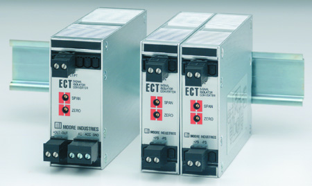
The ECT-DIN is a signal isolator, converter, repeater, booster and splitter and is available in 2-wire and 4-wire powered models with the ability to match the ECT to the type of AC or DC power available at each location, superior signal isolation up to 1500Vrms, and RFI/EMI protection.
The ECT-DIN also allows you to send the output from one transmitter to a second location. Additionally you can protect expensive monitoring/control equipment by eliminating common electrical paths or create a buffer between devices to allow interruption of one leg of a loop without impacting the other (see gallery image below for example). The ECT-DIN can even step down unsafe high level signals with an optional external input transformer (-EM option), allowing you to step down high level AC current inputs.
Do you want more information? Download the data sheet. Or visit the catalog.
Need to get price or availability or have a technical question?
Send us a message using E-Help.
 Q. I want to share a critical pressure signal with my DCS that is now part of our safety instrumented system (SIS) and have a two part question. First, do your isolators pass the HART diagnostic data that comes from my SIS smart pressure transmitter? Second, if there is a total failure of the pressure transmitter, where will the output of the isolator go to that is feeding my DCS?
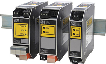
A. Yes, we have isolators that were designed specifically for these types of applications. The SSX and SST are exida approved SIL 3 capable isolators that pass HART data between any HART host or handheld device and the field transmitter. The second part of your question has two answers.
The SSX is an output loop powered isolator and as such when the input goes to 0mA the output will only drop to a minimum of about 2-2.5mA. The floor or minimum output is necessary because the SSX will need some level of current to keep its electronics circuit powered.
The SST is a four wire isolator so it behaves a bit differently. The SST’s output will follow the input through the entire range. For instance, if the input goes to 0mA or open circuit the output of the SST will follow the input all the way down to 0mA. Depending on your DCS settings, you can then choose when and how you want to alarm on the pressure transmitter’s health or loop status.
Download the data sheet to learn more about the SSX and SST.
 Q. Do you have a temperature control solution for a batch process chamber we have? We have a manufacturing process that uses a critical batch process chamber requiring an RTD that senses the temperature. When the process chamber is being used, we need to maintain temperature, so we have a secondary temperature monitor to help in case of a fail-over. To do this, I need to connect to our RTD that has dual 4-wire inputs and be able to switch from the primary to secondary if the primary is disconnected or fails.
A. You can use a Moore Industries’ THZ3-DIN temperature transmitter to precisely control the temperature. The THZ3-DIN can accept two 3-wire RTDs and can be configured so that its 4-20mA analog output is configured for failover/backup. If the primary RTD fails or is disconnected, the THZ3 automatically switches to the secondary RTD, it gives you a HART®alarm (and display an error if TDZ3 is used), and allows you to maintain the temperature measurement in the chamber.
You can use your existing 4-wire RTDs as 3-wire elements by taping off one of the leads. You will still have lead length compensation with the 3-wire RTDs as long as the leads are the similar length and have equal resistance.
The THZ3 can be configured by using a HART® hand held configurator or with PACTware running on a PC. A CDROM is provided with the PACTware installation files and DTM for the THZ3 with the shipment of the device. The THZ3 data sheet, manual, HART®DD, PACTware installation files, and the DTM are also available for download on Moore Industries site.
An easy-to-use yet robust Dual Input Smart HART® Temperature Transmitter, the THZ3 configures quickly and easily to accept a direct signal input from a wide array of sensors and analog devices including 14 RTD types and direct millivolt sources. The THZ3 has dual sensor input for Backup and Failover Protection, Average and Differential measurement and Low or High Select. It also has advanced RFI/EMI protection and ambient temperature compensation that helps guard against environmental factors that can quickly degrade measurement accuracy. Built-in 20 bit input resolution delivers exceptional digital accuracy of ±0.1°C (±0.18°F) with all Pt RTDs and is HART® 7 compliant with exception based reporting and dynamic variable mapping. There's even a High Availability Option that enables the user to select how the AO behaves when there is an input failure or out-of-range value detected by the transmitter that prevents nuisance alarms on startups.
Do you want more information? Download the data sheet. Or visit the catalog.
Need to get price or availability or have a technical question?
Send us a message using E-Help.
 Q. Can the PSD PC-programmable loop display pass HART® data without problems through the device if placed in a loop with a HART® capable transmitter?
A. The input of the PSD connects in series to the existing 4-20mA/HART®loop as if it was just an added resistance and only reads the analog 4-20MA signal. The PSD does not interfere with the HART®digital signal being transmitted on the loop.
Since the PSD does not have a path to ground or an output that could connect to another device, ground loops or other issues like extraneous conducted noise are not a problem.
However, when these loops do connect to devices that have separate ground paths or outputs problems can certainly arise. For these situations we recommend HART® pass-through isolators such as the HIX 2-wire output-loop powered unit or the HIT, a 4-wire mains powered isolator.
Moore Industries’ HART Isolators are a highly economical solution to common and costly problems that plague many of today’s “smart” process loops offering protection from surges, spikes, and transients up to 1500Vrms. You can safely share the HART® output of one transmitter with a secondary control or recording device allowing for redundancy without further burden or risk on a process loop. As an added bonus, you can perform equipment maintenance without loop downtime by isolating legs of the loop, making it possible to remove those instruments from the circuit without affecting other equipment. Protect and enhance your HART® investment with the 2-wire (loop powered) HIX or the 4-wire (line-mains powered) HIT.
Learn more about the HIT/HIX HART Isolator and the PSD PC-programmable Loop Display.
Do you want more information? Download the data sheet. Or visit the catalog.
Need to get price or availability or have a technical question?
Send us a message using E-Help.
 Q: A Type K thermocouple is being used in a high temperature furnace environment for temperature measurement. However the Type K thermocouple is drifting too much. Is there something I could do so I don't have to change it out frequently or is there another type of thermocouple I could use?
A: You could use a Type N with Inconel 600 Material, which is designed to perform well at high temperatures (over 2000F) and helps prevent corrosion in environments where atmospheres are reducing or alternately oxidizing and reducing. This would be particularly helpful for a furnace process that includes heating and cooling with moisture present, creating potential for oxidation to form from the process. Other high temperature environments that benefit from Type N with Inconel 600 Material include boilers and cookers processes or extreme environments where the thermocouple cannot be replaced easily.
In terms of their basic function, Type K and Type N thermocouples are similar. Type K is one of the most common type of general purpose thermocouple. However, the environmental setting that your thermocouple will be used in can affect your choice. Type N thermocouples provide a higher level of stability and durability in adverse environments than Type K thermocouples.
To be more specific, Type K thermocouples are susceptible to a phenomenon called Green Rot, or oxidation around the thermocouple. Green Rot is oxidation inside the thermocouple sheathing caused by operation at certain low oxygen environments, creating large negative calibration drifts leading to curve changes over time. Potential IR failure can happen, where the internal elements short and touch the outer sheathing due to oxidation (Green Rot).
Type N is also a viable choice when adverse environmental factors and high temperature requirements are an issue and there is difficulty in frequently changing out the thermocouple. While a Type N with Inconel 600 Material is only 20% higher in cost than Type K, the Type N can perform longer without the drift that oxidation causes, preventing the need to shut down the process to change out the oxidized thermocouple.
If you decide that Type N thermocouple isn't for you and are using a Type K thermocouple where your environment is the key factor instead of temperature, you can reduce the chances of Green Rot by increasing the oxygen supply through the use of larger diameter protecting tubes. The opposite approach can also work by inserting a mechanism to absorb oxygen inside a tube which can bring oxygen levels below what will promote oxidation.
Moore Industries can help when you are deciding if Type N is viable replacement for your Type K thermocouple application. You can contact us with your questions or if you need to know more about a product, price or availability.
Do you want more information? Download the data sheet. Or visit the catalog.
Need to get price or availability or have a technical question?
Send us a message using E-Help.
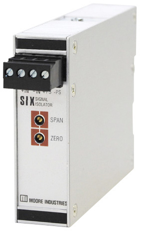
Q. I have two different control systems and I need some splitters to split a 4-20 mA signal. I may need to have the loop isolated. Can you help specify a splitter that can send the signal to both control systems where I can use the splitter connected in a series on the original loop? My company has used the SIX in the past, would this work?
A. The SIX can be used in a “splitter” application when its input is connected in series on the original loop. The output of the SIX 2-Wire Signal Isolator/Converter gives you the isolated loop. The versatile SIX can be used as a signal isolator, converter, and repeater. It is an excellent choice for installation in the plant or control room. The 2-wire (loop-powered) SIX derives its power from the output loop, eliminating the need to install an additional power supply.
If you decide you need to have the two control systems isolated from the original signal, then you can use the ECT-DIN model ECT/4-20MA/2X4-20MA/117AC* [DIN] Signal Isolator, Converter, Repeater, Booster and Splitter for more versatility. The ECT-DIN features a solid metal housing that stands up to the continuous, daily rigors of process control and factory automation applications.
Like the SIX, the ECT's input is wired in series with your original loop. The ECT then gives two separate and isolated outputs for your two control systems. Each output is capable of driving 600 ohms of output load. This version of the ECT also offers a TX option that powers a two-wire transmitter connected to its input.
If you have functional safety in mind, the SSX/SST Model number SST/4-20MA/2X4-20MA/117AC* [DIN] works like the ECT but is part of Moore Industries’ FS Functional Safety Series. The SSX/SST Safety Series Isolator and Splitters are exida® approved, SIL 3 capable. The SSX is 2-wire (loop powered), and the SST is 4-wire (line/mains powered). The SSX/SST provides isolation and signal conversion for your SIS (Safety Instrumented System) needs. These units protect and enhance loops and also pass valuable HART® data from the field transmitter to host systems and vice-versa.
The ECT and SST are line powered and supply the voltage to their outputs, so the control systems receiving their outputs must have passive inputs. If your control system inputs are active (providing power), contact us and we can modify the ECT or SST for those loops too.
Other things to consider:
Do you need to pass digital HART signals between the input and outputs?
- The ECT filters the HART component
- The SST passes HART on the outputs (both or neither)
- The SST is from our line of Functional Safety products
Do you want more information? Download the data sheet. Or visit the catalog.
Need to get price or availability or have a technical question?
Send us a message using E-Help.
Q: Is there a less complicated and economical solution to replace a failed thermocouple than a complete shutdown of a boiler?
A: To address this issue, we need to note that furnaces, boilers, and reactors present an interesting problem when trying to replace a failed thermocouple. Typically to replace thermocouple sensors, the entire furnace or boiler must be shut down for long periods of time creating downtime and lower productivity. Most facilities will try to schedule this type of shut down once every 4 to 5 years because shutdowns are time consuming and costly. Once the boiler is down, most customers will remove all of the sensors, and perform a full replacement, to prevent shutdowns for as long as possible. Facility maintenance personnel with special training in “Small Space Confinement” must do the replacements.
Because this kind of replacement is costly in both downtime and new sensors, if a sensor fails, that particular temperature measurement is lost until the next maintenance schedule. A facility will not shutdown a boiler earlier than originally scheduled even if more than 50% of the sensors fail before the maintenance schedule, unless there is a critical safety issue requiring shutdown.
Thermocouples are long, typically about 20 to 40 feet long. They have a small metal pad welded to the tip of the sensors sheath with the weld pads tack welded to the surface of the Protection Tube (pipe) inside the high-temperature area making them typically expensive to replace.
Moore Industries has a simple and economical solution to this complicated process: The WORM Flexible Temperature Sensor. It lets you replace the sensor without removing the Protection Tube or disassembling the thermowell by just replacing the broken sensor. The High Temperature WORM is a flexible sensor for thermowell temperature assemblies that is available in standard sensor types including 100 and 1000 ohm platinum, nickel and copper RTDs, and J-, K-, T-, E- type thermocouples with step response times 13% faster than standard sensors. The WORM comes in a universal length so there’s no need to stock an expensive array of different sensor lengths. With a quick measurement and a simple trim-to-length, the WORM handles nearly every thermowell assembly.
For boiler tube applications, the WORM ships with a hollow protection tube that includes a weld pad with a thermocouple WORM Sensor that enables sensor replacement from outside of a boiler. The tube is hollow and allows a flexible Worm Sensor to slide down inside the Protection Tube from outside the boiler. This allows the customer to replace a sensor, if it should fail, anytime while the furnace is still up and running.
Do you want more information? Download the data sheet. Or visit the catalog.
Need to get price or availability or have a technical question?
Send us a message using E-Help.
Q. Is there a signal conditioner with 0-2Vdc input and two isolated 4-20mA outputs with 24Vdc? I need it as compact as possible because I need to install it horizontally in a cabinet.
A. The ECT-DIN series dual 4-20mA output can be provided with a modified input to accept a 0-2Vdc signal. Moore Industries offers a build option from the factory (the ECT which acts as a Splitter). The model number for an ECT with this configuration is ECT/0-2V/2X4-20MA/24DC [DIN]. Typical installation of an ECT is a DIN mount so the housing we offer is a DIN-style housing which mounts on 32mm G-type (EN50035) and 35mm Top Hat (EN50022) rails.
The ECT-DIN is rugged as well as reliable and is available in 2-wire (loop) or 4-wire (line/mains) powered models.
The complete family delivers economical solutions for an expansive range of signal interface applications such as protecting equipment and signals by eliminating common electrical paths, amplify signals allowing more instruments on an overburdened loop, isolate signals to prevent erratic measurements, convert signals so field devices can interface with equipment such as an indicator or PC-based SCADA system, split one signal to allow one primary measurement to be sent to two separate systems, and solve bucking power supplies. The ECT has superior signal isolation up to 1500Vrms and stops ground loops, motor noise, and other electrical interference from affecting process signals.
For more information on the ECT, view the product page.
Do you want more information? Download the data sheet. Or visit the catalog.
Need to get price or availability or have a technical question?
Send us a message using E-Help.
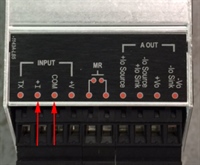 Q. Can the SPA2 be placed in an existing 4-20mA loop as passive?
A. The SPA2 can be wired using the passive input (+I and COM) in series in your 4-20mA loop. It will add about 20 ohms to the loop.
When ordered with the Analog Output (-AO) option, the SPA2 provides a proportional and isolated analog retransmission of the input signal that can be sent to remote monitoring/control devices like a DCS, PLC, PC, indicator or data recorder, making it completely isolated from the input. All analog parameters can be selected using the SPA2 push buttons or the free easy-to-use Intelligent PC Configuration Software.
The SPA2 Programmable Limit Alarm Trips provide on/off control, warn of unwanted process conditions, alarm on rate-of-change, and provide emergency shutdown. Very versatile, the SPA2 accepts a signal input from transmitters, temperature sensors, and a wide array of other monitoring and control instruments such as current and voltage signals, 23 RTD Types, 9 Thermocouple Types, resistance and potentiometer devices, and Direct Millivolt Sources. Features of the SPA2 include 20-bit input resolution, long-term stability with up to 5 years between calibrations, large 5-digit process and status readout, and isolated RFI/EMI protection.
Do you want more information? Download the data sheet. Or visit the catalog.
Need to get price or availability or have a technical question?
Send us a message using E-Help.
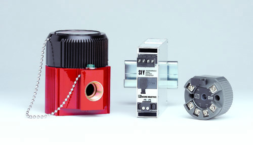 Q. Currently, I have an application where I need to configure my SIY input to 0-1mA. Is this possible?
A. Yes, the minimum input span possible on the SIY is 1 mA, allowing you to configure it to 0-1 mA.
Not only can you configure the SIY to 0-1 mA, the enhanced configuration software allows you to trim input sensor readings, customize input linearization curves, program output damping, and calibrate other loop instruments. The SIY handles the majority of current/voltage interface applications you are likely to encounter.
Moore Industries’ SIY PC-Programmable Signal Isolator/Converter combines smart digital technology with advanced analog operation to deliver superior reliability, accuracy, and ease of use. To learn more about the SIY visit our website.
Do you want more information? Download the data sheet. Or visit the catalog.
Need to get price or availability or have a technical question?
Send us a message using E-Help.
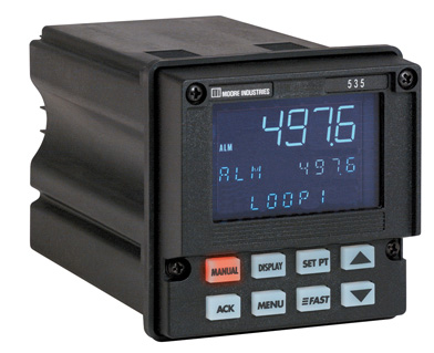 Q. When the 535 1/4 DIN Single Loop PID Process Controller loses power with remote setpoint on, it comes back up in local setpoint mode. Is there a way to have the 535 always come back up in remote setpoint mode when power is restored?
A. Yes, the 535 can come back up with remote setpoint. To make the 535 power up using remote setpoint:
In the configurations menu
- Go to the SPECIALmenu
- Go to PWR. UP: SP
- Select REMOTE
Details are on page 51 (number on the bottom right or page 58 of the PDF) in the user manual. For your convenience, the image is attached at the bottom of this page.
Check out more on the 535 1/4 DIN Single Loop PID Process Controller.
Do you want more information? Download the data sheet. Or visit the catalog.
Need to get price or availability or have a technical question?
Send us a message using E-Help.
Q. As part of a power distribution process I need a dual signal isolator/converter/splitter that has an input of 0-1mA, outputs of 0-1mA and 4-20mA with 117VAC power input? It needs a DIN housing so it can be mounted in an existing cabinet.
A. Moore Industries has the ECT Signal Isolator, Converter, Repeater, Booster and Splitter and comes in 2-wire (Input-Loop Powered) and 4-wire (Line/ Mains Powered) versions with input 0-1mA, with outputs 0-1mA and 4-20mA, with 117VAC power input in an aluminum DIN rail mounted housing.
- When ordering, specify the model number in this format: Unit / Input / Output / Power / Options [Housing]
- To order the model discussed use this model number: ECT/0-1MA/0-1MA,4-20MA/117AC [DIN]
Moore Industries also offers optional NIST Traceable Test Reports with recorded test data.
To read more on the ECT or on other products please go to our website
Do you want more information? Download the data sheet. Or visit the catalog.
Need to get price or availability or have a technical question?
Send us a message using E-Help.
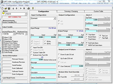
Q. On a 4-20mA gas detector, while we replace the cell, the output reverts to 3mA. This causes the device receiving the 4-20mA signal to go into a critical alarm condition and can shut down a critical process. What device do you have that will keep the output at no less then 4mA? It would also be convenient to have this instrument provide me with a relay alarm contact output when my input goes to 3mA. It can be 24Vdc or 120Vac. It should be in a DIN housing.
A. Moore Industries CPT PC-Programmable Temperature Transmitter and Signal Isolator/Converter CPT/HLPRG/0-20MA/117AC/-C [DIN] can be used for this application.The selected model allows you to limit the minimum and maximum output, even when you are replacing the cell. The alarm relay option allows you to set an alarm at whatever level below 4mA for maintenance notification. Figure 1 below shows a configuration that would work for your application. A configuration cable is required to utilize the PC programming capability.
The CPT has a menu selection for upper and lower limits. You can set the low alarm limit there, such as 3.5mA.
Figure 1. CPT PC Configuration
Do you want more information? Download the data sheet. Or visit the catalog.
Need to get price or availability or have a technical question?
Send us a message using E-Help.
Q: I want to use a SIX Signal Isolator/Converter in a loop with a cable run of 1200’. Are there cable parameter values (i.e. maximum inductance/capacitance) that must be met in order to maintain the FM Non-Incendive certification?
A: The certification by FM of the SIX for Non-Incendive Class 1 Div 2 does not include any cabling restrictions. The maximum cable length is a function of the available compliance voltage and the total resistance (loss in the wire and device loads).
Do you want more information? Download the data sheet. Or visit the catalog.
Need to get price or availability or have a technical question?
Send us a message using E-Help.
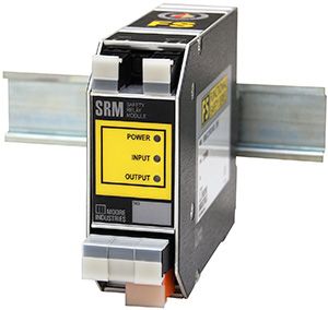 Q: The SRM Safety Relay Module only has three contacts. Is it possible to add extra contacts? Also, is there specific wiring required to obtain a SIL 2 rating?
A: You can connect a wetted contact to the power terminals of two SRMs in order to have more than three contact outputs. Connect jumper wires to the input terminals of these SRMs. The wetting current must be sufficient to drive the coils of the two SRMs.
The SRM installation manual has detailed directions for installation in Safety Instrumented Systems (SIS) as well as information about connecting the coil (input) side to either dry or wetted contacts. In addition, Figure 5.3 in the manual shows how to connect a wetted contact to a single SRM.
Do you want more information? Download the data sheet. Or visit the catalog.
Need to get price or availability or have a technical question?
Send us a message using E-Help.
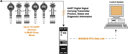
Q: We are interested in your HCS HART Concentrator System. What are the options for converting a single HART transmitter or for converting 16 transmitters with one unit?
A: You don’t have to choose between connecting one or multiple transmitters to the HCS. A single HCS unit can be configured by the user to interface with a single drop HART loop (one HART device) or to a multi-drop HART loop (2 to 16 HART devices).
In point-to-point HART mode, the HCS is set to monitor a single instrument. All process and diagnostic data carried on the HART data string is converted to MODBUS RTU.
In a digital multidrop HART network, up to 16 HART instruments digitally communicate on the same wires. The HCS can be set to monitor any or all instruments and/or valves within the network. Only one MODBUS address, and one communication link (such as twisted wire pair), is needed to send the process and diagnostic data from up to 16 HART devices to a MODBUS host.
Do you want more information? Download the data sheet. Or visit the catalog.
Need to get price or availability or have a technical question?
Send us a message using E-Help.
Q: We have been using the ECT-DIN in our applications where we need to split one 4-20mA input to two outputs. The model number for our current units is ECT/4-20MA/2X4-20MA/117AC/DIN. We now need to split a signal to three outputs. Do you have a product that will help us to do this?
A: If you need the splitter to provide the loop voltage for the third 4-20mA output, as you did in the previous installation, you can use two of the ECT/4-20MA/2X4-20MA/117AC/-TX [DIN] models and wire your 4-20mA in series to each of the ECT's inputs. This will provide you with up to four isolated outputs. This ECT model also comes standard with a -TX option which provides loop power, if required, to a power a two-wire transmitter.
An alternative option would be to use our MIX four channel isolator, model number MIX/4X4-20MA/4X4-20MA/12-42DC [DIN]. The input signal needs to be connected in series to at least three of the four inputs to meet your requirements. This option will also provide you with one spare channel.
It is important to note that your receiving device will need to provide the loop power for each channel since each of the four MIX channels are output loop powered (passive outputs).
Do you want more information? Download the data sheet. Or visit the catalog.
Need to get price or availability or have a technical question?
Send us a message using E-Help.
 Q: Will the SIX Signal Isolator/Converter pass input signals through if the output is disconnected? We will be replacing our DCS, so we need to know if the input side will continue to work while the DCS is disconnected.
A: The SIX’s input has a passive 50 ohm resistance. Connecting the input of the SIX in series with the loop is the same as adding a 50 ohm resistor. This passive resistance is maintained whether the SIX’s output is receiving power or not.
Stay up-to-date on future developments and enhancements on this product and our other product lines, sign up for our customer newsletter.
Do you want more information? Download the data sheet. Or visit the catalog.
Need to get price or availability or have a technical question?
Send us a message using E-Help.
Q: Does the WORM Flexible Sensor RTD have a 3-wire option? If not, can I eliminate the fourth wire by jumping two of the parallel wires together?
A: Yes to both questions. If your transmitter or other measurement can only deal with a three-wire RTD, you can stow the orphan lead or connect it to the other wire of the same color. The alternative is to purchase a special three-wire version of the WORM RTD. However, to achieve greater measurement accuracy we recommend using a 4-wire RTD. You can learn more about the benefits of 4-wire RTDs and other ways to improve accuracy in our A Practical Guide to Improving Temperature Measurement Accuracy white paper.
Do you want more information? Download the data sheet. Or visit the catalog.
Need to get price or availability or have a technical question?
Send us a message using E-Help.
 Q: We currently are using TCA Thermocouple Alarm units in our plant (model TCA/K-10MV/SX1/117AC/[STD]). The user’s manual says that the deadband is fixed at 1% of the input range. However, we need the TCA to trip at a set point of 190°F and reset at 180°F. Is this model capable of meeting this requirement and do you still manufacture this model?
A: Your model with the 1% deadband is not sufficient to handle the application. The model you need requires the Adjustable Deadband (-AD) option, which provides you a deadband adjustment of 1-20%. If you have a need for a larger deadband, the factory can assist you with selecting a newer microprocessor-based alarm module featuring increased configurability.
Do you want more information? Download the data sheet. Or visit the catalog.
Need to get price or availability or have a technical question?
Send us a message using E-Help.
Q: In specifying the Moore STA / HLPRG / 3PRG / U / -AO [DIN] our end user has a concern about electrical protection for the analog output. The desire is to use 4-20mA Output Loop Voltage sourced by DCS for the AO; however, this voltage may fault at up to 132 VAC. Should our design add fuse protection in the external voltage circuit upstream of the STA to protect it from these surges? Or does the STA include features that protect it from these faults?
A: A fuse will limit current but not excessive voltage. If the DCS cannot be configured for a sinking input, then I recommend using a “sacrificial” isolator. Connect the sourced output of the STA into the input of an output loop powered isolator. The output of the isolator goes to the DCS’s sourcing input. If there is a 132V fault voltage from the DCS, it will risk damaging the isolator and not the STA.
An example of such an isolator that would work is an ECT/4-20MA/4-20MA/12-42DC [DIN].
If this analog output from the STA is part of a safety path, then consider using the SSX/4-20MA/4-20MA/12-42DC [DIN] as it is a Functional Safety isolator designed for safety instrumented systems.
Download the ECT-DIN data sheet for more information.
Do you want more information? Download the data sheet. Or visit the catalog.
Need to get price or availability or have a technical question?
Send us a message using E-Help.
Q: Do you have a signal alarm unit for a tank level application? I need it to meet the following requirements:
- Input signal accepts 4-20mA.
- Contacts opened or relay de-energized @ EL 208 ft.
- Equipped with up to four alarm trip relays.
- Individually configured for: set point, high or low trip, normally open or normally close, failsafe or non-failsafe, and latching or non-latching.
- Deadbands adjustable over 100% of span.
- Output relay equipped with form C contacts rated at 10A, 120VAC.
- All operating parameters adjustable from the front panel keypad.
- Operate on a 120V 60 Hz power source.
- Capable of supplying 24V dc power to two-wire transmitters.
A: This is a perfect match for the Moore Industries SPA2 alarm trip unit. The SPA2 can handle all of your above requirements, with an exception and a clarification. Alarm set points for 208 feet should not be a problem assuming you have ranged your 4-20mA input to equal some engineering unit range of at least 208 feet, i.e. 4-20mA = 0-500 feet. The exception is with the the form C relays on the SPA2. They are rated for 5A, not 10A. Therefore, if you need a 10A relay we recommend using an interposing relay in conjunction with the SPA2 outputs. An example model number is: SPA2/HLPRG/4PRG/U [DIN]
Do you want more information? Download the data sheet. Or visit the catalog.
Need to get price or availability or have a technical question?
Send us a message using E-Help.
Q: HIX Application - It appears that if the "Primary Master" loop (input loop side of the HIX) is broken or open circuited, the "Secondary" loop (output loop side of the HIX) will be 0mA. Is this true? Maybe I can put a zener across the primary process terminals to keep the current loop when the process opens? Also, are both or either loops bi-directional HART? I have a 4-20mA input signal that I'd like to share between two 4-20mA/HART process loops. Actually, we currently use another vendor's device to "split" one 4-20mA input to four process loops but it doesn't pass HART.
A: The HIX is an output loop powered device that is an analog circuit, so the output will follow the input as far down as possible. If the input goes to zero mA on the HIX input circuit, the output will go down to about 2mA, but not all the way down to zero. This is due to the active parts of the power supply circuit, on the output side of the HIX, that continue to consume some trickle power to keep the unit “alive”. Yes, the HIX supports bi-directional HART communication.
If you are looking for a single input, dual output device that passes HART, then take a look at the SST series. Utilizing two of these SST splitters will offer you the four process loops with HART pass through capability. This device also supports bi-directional HART communication.
The outputs of the dual output SST normally source the loop voltage, but there is an option to make both outputs “passive”.
Download the HIX/HIT data sheet or the SST data sheet.
Do you want more information? Download the data sheet. Or visit the catalog.
Need to get price or availability or have a technical question?
Send us a message using E-Help.
 Q: I have a project for six RTD measurements that makes using standard fixed length sensors difficult because there is little clearance near the top of the thermowell for sensor insertion. It looks like your “WORM Sensor” would be an ideal fit for the application because of its flexible design. These RTD sensors need to be 100 or 1000 ohm platinum elements with Class A or 1/3 DIN accuracy ratings. They will be used to monitor chilled and hot water lines with min and max temperature limits of 30 F and 180 F. Maximum insertion length in these ¼ inch ID thermowells is about 10 inches. I noticed that your standard WORM length is 24 or 36 inches. Are custom length WORM sensors available? If so, what cost is associated with ordering multiple sensors at custom lengths? Lastly, we usually request test data with all of our sensors and check them in our air bath or heat block calibration units. Can you offer a test report or test data points with these WORM sensors?
A: We stock the WORM Sensor in standard lengths of 24 and 36 inches for quickest delivery. At any time, you can order shorter lengths at any quantity at no additional cost. However, one of the many unique advantages of the WORM sensor is that it is field-trimmable. All that you need to do to shorten the insertion length of any WORM sensor is trim the length of the spring and lead wires. This makes it the perfect sensor for stores or stockroom. If you need a WORM sensor longer than 24 or 36 inches, contact us and we can build custom length WORMs to match your application requirements.
 The 24 and 36 inch WORM sensors are sold separately or you can save money if you purchase our prepackaged WORMs in a three pack or 10 pack. The 10 pack of sensors, called the “Can of WORMS”, offers the greatest cost savings for your application of six elements. The WORM sensor was designed to handle two temperature ranges: Standard and High Temperature, designated respectively by “WS” and “WH” in the model number. The temperature limits in your application can easily be handled by the WS standard WORM element.
With regard to sensor accuracy, we only build our RTD sensors to meet the newest IEC 60751 standards. This standard addresses the requirements needed to meet tolerance levels required for different classes of RTDs that include Class AA, A, B and C. Moore Industries only supplies Class AA and A sensors when increased accuracy or calibration requests are mode on sensors and assemblies. Additionally we thermally age our sensors for 1,000 hours. When the RTD element is temperature aged, it ensures that the platinum substrate material inside the sealed element will provide a more stable and long term repeatable output. This helps reduce the frequency of transmitter and input card calibration due to sensor drifting.
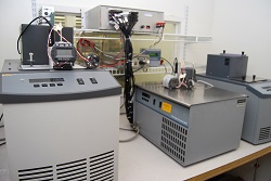
Moore Industries offers certified calibration services for sensors and sensor-transmitter assemblies. For your application we can offer you a –VTD calibration option. With this option we will use our NIST traceable oil calibration bath to take and record five temperature/resistance points within your requested temperature range, and offer a test data report. This test report will list the sensor serial number, date of calibration and all of the NIST traceable calibration equipment we used to perform the test.
Most often our customers request that we calibrate and certify the full temperature assembly, using our –VTB option. This offers the best accuracy since we are matching your sensor to the transmitter and calibrating them as an overall measurement assembly or system. We only certify these assemblies utilizing Class A (.06%) or Class AA (.04%) sensors since they drift less and offer the most long term repeatable measurements.
For customers who are required to validate accuracy performance on a regular cycle, our -VTB calibration option reduces the need to calibrate so often. In many cases customers do not have the equipment with the required accuracy levels to perform onsite calibrations. Moreover, the cost of calibration performed by us is only a fraction of the cost that it would cost them.
Get the details on Moore Industries WORM Flexible Sensors. Download the Get Rid of Rigid technical paper for insights to using flexible sensors, and the WORM data sheet.
Do you want more information? Download the data sheet. Or visit the catalog.
Need to get price or availability or have a technical question?
Send us a message using E-Help.
 Q: We want three 100 ohm, .00385 Alpha RTDs to measure heated glucose in railroad cars. We heat the glucose to 140-150°F, and want to use a 5-foot long flexible sensor with a head on top containing a terminal strip. We also want to run flexible conduit from the head with copper wire for easy replacement access. We can fabricate a bracket that would span the midway above the railcar that supports the housings and includes holes that allow the flexible RTDs to drop down for installation. What do you offer that is a fit for our application?
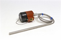
A: Moore Industries has several variations of its WORM sensor precisely for liquid measurement applications. Using the WORM with our specially-designed 12-inch weighted bar, which is potted at the end of its capsule, offers stability from swinging or moving when suspended in liquids. We also offer a -30G potted option which provides added protection from extreme shock in harsh environments.
One of the best features of this assembly is the Teflon insulated leads sealed inside a Teflon jacket. This protects the lead wires from liquids penetrating the insulation and potentially causing shorts. For maximum protection against very harsh abrasive environments, we have also added flex armor cable over the Teflon jacketed leads. Flex armor also acts as an additional weight to the entire assembly yet is still flexible enough to raise and lower the tip of the WORM.
Another feature of this assembly is the 0.50-inch outside diameter of the weighted bar. This allows insertion of the bar through a ½-inch NPT threaded hole for easy installation.
At the transmitter where the lead wires enter the housing, we use a sealed stainless steel sleeve attached to the flex armor cable which is sealed at the lead wires. This provides a sealed and rigid spot where we add a compression fitting for securing the assembly to the housing. In addition this sleeve and compression fitting allow the installer to adjust the depth of the WORM assembly.
For additional reading on Moore Industries’ WORM Flexible Temperature Transmitter, download these white papers: Measuring Molasses with the WORM and Get Rid of Rigid.
Do you want more information? Download the data sheet. Or visit the catalog.
Need to get price or availability or have a technical question?
Send us a message using E-Help.
 Q: We want to install an
STA / HLPRG / 3PRG / U / -AO [DIN] into our process and plan to use 4-20mA output loop voltage sourced by a DCS for the analog output, however this voltage may fault at up to 132 VAC. Should we design in fuse protection to the external voltage circuit upstream of the STA to protect it from these surges? Or does the STA include features that protect it from these faults?
A: A fuse will limit current but not excessive voltage. If the DCS cannot be configured for a sinking input, then we recommend using a “sacrificial” isolator.
To do this, connect the sourced output of the STA to the input of an output loop powered isolator. The output of the isolator goes to the sourcing input of the DCS. If there is a 132V fault voltage from the DCS, it will risk damaging the isolator and not the STA.
For information on the STA, download the data sheet.
Do you want more information? Download the data sheet. Or visit the catalog.
Need to get price or availability or have a technical question?
Send us a message using E-Help.
 Q. What is the least expensive way to speed up the response time of a sensor installed inside of a thermowell? We have a reactor associated with a quickly changing process and need to be able to control any sudden changes. What do you suggest?
A. We can suggest several solutions:
If you reduce the mass of the thermowell stem, which is the portion inserted into the process, sensitivity to the response will increase.
Another option is to add temperature sensitive paste to the inside of the thermowell to fill in the air space and allow temperature changes to more quickly conduct to the sensor sheath.
Our last recommendation is to reduce the sheath length, which you can do by using one of Moore Industries’ WORM flexible temperature sensors. The WORM has a very short sheath length of 1.5-inches and responds to temperature changes 13% faster than a longer fixed sheath. (Keep in mind: The longer the sheath length the longer the response time). Also, reducing the sheath diameter will speed up response. The WORM sensor also has a reduced tip outside diameter (OD) of 6mm. The shorter and smaller the OD of the sheath, the faster the response rate. Replacing your existing sensor with the WORM sensor should immediately show improved response time.
To read more about the WORM, download the data sheet.
You can also download the Getting Rid of Rigid White Paper for insights to using flexible sensors.
Do you want more information? Download the data sheet. Or visit the catalog.
Need to get price or availability or have a technical question?
Send us a message using E-Help.
 Q: We have several outdoor temperature applications where we measure the temperatures of pipes running alongside cooling towers. These sensors are in several different locations and zip-tied to the outer surface of the cooling pipes. Our problem has been that exposure to rain, sun and heavy snow causes signals to drop off or spike. We believe moisture is getting into the wire jacket and the environmental exposure is causing false readings. The sensors we use have a PVC jacket over the lead wires and it shows cracking over time. We need to replace the sensors and would like a 4-20mA output signal to go from our junction box out to the field instead of running the sensor lead wires all the way back to our monitoring system. What type of solution do you have for this?
A: Surface mounted temperature measurements is an area Moore Industries excels in and we build a variety of mountable measurement devices. Our WORM sensors offer Flex Armor Cable or Stainless Steel braid options to provide greater protection from exposure. Also, we offer sensors that have Teflon insulated leads with a Teflon jacket that can withstand liquids and provide protection from cracking with a temperature tolerance from -200 to +500°F.
To secure the WORM sensor to your pipe, use our “CLAMP” fitting which uses a pipe band for a secure fit. We can add Flex Armor over the Teflon jacket and run it along the surface of the pipe and back to your junction box. At the junction box you can install one of our TRY/TRX or THZ3 two-wire loop powered Hockey Puck (HP) housed temperature transmitters to achieve a 4-20mA output that can be wired back to your monitoring system over your existing lead wires (we also have additional installation options if an HP transmitter will not fit in your existing junction box).
Do you want more information? Download the data sheet. Or visit the catalog.
Need to get price or availability or have a technical question?
Send us a message using E-Help.
Q: Currently we monitor the temperature level in our oven with a thermocouple and let our PLC control the oven. We now need to implement a high-temperature Safety Instrumented Function (SIF). Do we need duplicate temperature sensors and do you have a Functional Safety device that can provide oven shutdown capability on high temperature?
A: A requirement of the SIF is for a safety function to be independent from the control system with the expectation that the safety loop will not fail should the regular process control loop incur a sensor, controller or any other failure. Therefore, it is recommended you not use the same sensing devices (thermocouple in your instance) for the safety function and control system. Other considerations to factor in are maintenance and proof testing of the SIF. If either affects the control system, interruptions to normal operation during this time will be experienced. If a common sensor is used, then a risk analysis must be performed.(Please refer to IEC61508 standard section 7.4.2.3 and ISA84/IEC61511 Part 1 11.2.10 and Part 2 11.2 for more information.)
To maintain a safe, operable system, SIL (Safety Integrity Level) guidelines state that your SIF would have an independent temperature sensor housed in a different thermowell. For improved safety, use of different technologies for these sensors avoids common cause failures in the control and safety functions; either different types of thermocouples or an RTD if temperature limits allow. Best practice is to duplicate transmission of the safety sensor signals to the control system. Such an arrangement can lead to improved diagnostic coverage by allowing signal comparison between control and safety sensors.
For this SIF, we recommended using products from Moore Industries’ Functional Safety Series which are independently assessed and certified by exida. The STA Functional Safety Trip Alarm can be used to monitor the oven’s thermocouple sensor and includes two user-configurable failsafe process trip alarms. It also has an isolated 4-20mA analog output signal which can be sent to the primary control system for comparison with the process control temperature signal.
If additional process relay outputs are required you can use the SRM Functional Safety Relay Module. The SRM accepts an input from one of the STA process relay outputs and offers three additional relays that can be used to drive other output loads.
The STA Functional Safety Trip Alarm and SRM Functional Safety Relay Module are available with IEC 61508 certificates from exida, safety manuals and FMEDA reports for your SIF calculations.
For more questions regarding application concerns and compatibility, contact us at
E-HELP EXPRESS.
Do you want more information? Download the data sheet. Or visit the catalog.
Need to get price or availability or have a technical question?
Send us a message using E-Help.
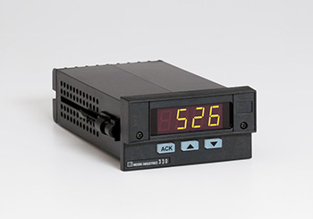 Q: My Model 330R process monitor with display has configurable threshold output relays that I need to set in order to activate a 125Vdc battery powered circuit which is part of a failsafe control room application. How would I set these up when standard instrument relays are rated at 125/240Vac and 24Vac/dc?
A: The Model 330R process monitor threshold alarm relays are ‘compact’ relays designed to activate ‘external intermediate’ relays. High DC voltage (and/or current) switching is always performed on the output contacts of a stand-alone external intermediate relay because high voltage DC switching (opening of relay contacts) creates a sustained high temperature plasma arc. This arc cannot be readily extinguished in a small instrument package, therefore, the relay sacrificially absorbs the excess energy. This ultimately requires replacement of the relay however this is a more economical alternative to replacing a blown panel meter.
A proven solution for the high DC current at high voltages need is to use Form ‘X’ style relays with a built-in magnet (this is a readily available industrial relay product which also comes in a DPDT configuration) as your intermediate relays. The coils of these intermediate relays are driven by the standard voltage/current relays as in the Model 330R series. A quick Internet search of ‘Form X relay schematic’ will provide you with wiring instructions.
A Form X relay has an optional magnet (recommended for DC voltage applications). As the relay opens, a small to moderate sized electrical plasma arc always occurs. The magnet pushes the arc away from a straight line and onto a longer distance pathway. Thus the Form X relay’s mechanical doubling of contact separation distance along with the properties of the installed magnet significantly increase the arc travel distance and more quickly extinguish the DC plasma arc. When wiring for DC switching, be mindful of the polarity of the electrical contact pathway through the magnetic field to ensure that you are extending the arc distance.
To optimally select a Form X relay:
- Perform an Internet search for ‘Form X relay with magnetic blowout’
- Specify a clear relay package referred to as an ‘ice cube’. This permits visual inspection of the relay’s internal movements.
- Specify the relay ice cube package with either a DIN rail socket or a panel mount socket with a retaining clip so the relay does not fall out of the socket as may occur in high vibration applications.
To learn more about the Model 330R, download the datasheet.
Do you want more information? Download the data sheet. Or visit the catalog.
Need to get price or availability or have a technical question?
Send us a message using E-Help.
Q. We have several short thermowells in our process, ranging from 2-inches to 6-inches. Our process is very stable, but we have noticed a temperature measurement shift when the outside air temperature rises or falls. We have tried calibration, but it still doesn’t correct the temperature swing we see. What would you suggest we change that will prevent these temperature swings?
A. The most active area of a sensor can be approximated as 4 to 10 times the length of the installed element. As temperatures change outside the process, the upper portion of the sheath is exposed to these fluctuations. This part of the sheath senses a temperature difference then measures it, influencing the temperature along the full length of the sheath. We regularly see this occurrence when calibrating sensors with long sheath length exposed outside of calibration baths. The only way to measure true process temperature is to keep the sheath as short as possible.
Moore Industries manufactures the WORM, a sensor with a very short sheath length of 1.5-inches. Worm sensors are spring loaded to stay at the bottom of the thermowell. They have a faster response time and the lead wires do not measure temperature changes outside the process connection. They do not sense any outside temperature swings and only measure temperature inside the bottom area of the thermowell.
To read more about the WORM, download the data sheet.
You can also download the Get Rid of Rigid White Paper for more information on using the WORM in your process.
Do you want more information? Download the data sheet. Or visit the catalog.
Need to get price or availability or have a technical question?
Send us a message using E-Help.
Q: We need to combine a new system for reading tank levels with an existing system by replacing a Hagan instrument with a new Rosemount device. However, we need to ensure we can still run an existing 3-27psi pneumatic chart recorder. We’re considering using an I/P, but aren’t sure if the 4-20mA output from the new transmitter can be piggybacked. Is this possible?
A: If the 4-20mA loop can drive the load presented by Moore Industries’ I/P then you can piggyback the output and run your chart recorder. Our model IPT2 (DIN rail mounted) consumes 7.5V of the available loop compliance voltage. Our model IPX2 (field mounted) consumes 5V of the available loop compliance voltage. Both models offer a 3-27psi output.
For additional information, download the datasheet: IPT2 and IPX2.
Do you want more information? Download the data sheet. Or visit the catalog.
Need to get price or availability or have a technical question?
Send us a message using E-Help.
Q: You have a product called HART Interface Module (HIM) that will pull the 2nd, 3rd and 4th HART variables from a transmitter signal and create one 4-20mA signal for each. Do you have or know of an instrument that will take multiple 4-20mA signals and output them on one 4-20mA signal as HART dynamic variables? I would like to read three transmitters on one 4-20mA signal by reading the variables on my DCS system.
A: We have two products that take multiple inputs and output a HART signal that can be read by a HART host. Those two products are the TCM and the THZ3/TDZ3.
The TCM is a 16 channel input module that accepts multiple temperature, resistance and millivolt signals and offers a HART output or a MODBUS RTU output. For 4-20mA inputs the TCM accepts them across a resistor or shunt input as a mV input. Those signals can then be read by a HART host using a custom HART command. For a MODBUS RTU output a separate HART to MODBUS converter, called the HMC, is used. For more information on the TCM and HMC (which together comprise the TCS) download the TCS data sheet.
The THZ3/TDZ3 Smart HART Temperature Transmitter can accept two (not three) 4-20mA
signals and write them to two of the HART dynamic variables riding on the analog 4-20mA
output.
A wiring diagram showing how to wire the THZ3 to accept two 4-20mA input signals is available in the Installation Manual which you can download here. For more information, download the THZ3 data sheet.
For more information on the HIM, download the data sheet.
Q. We have been using 3-wire RTDs in our process for years and are required to check the calibration once every 6 months. Each time we have checked the sensors we’ve noticed they have drifted. This requires us to re-calibrate our temperature transmitters. Do you have something you can suggest to help us reduce the drifting problem we regularly see in these sensors?
A. The problem with 3-wire RTDs is that the lead wires build up small amounts of corrosion causing a lead wire imbalance which results in measurement errors. If these are Platinum 100 ohm RTDs, just one ohm of resistance change on any lead wire can represent a +4.7°F degree error. We suggest using 4-wire RTDs which compensate for unequal resistance in the lead wires. For this to be an option your temperature transmitters need to accept a true 4-wire sensor input. Some temperature transmitters, PLCs, and DCS input cards only accept 3-wire RTDs. Others indicate a place to connect a fourth wire, but do not use it for measurement.
You can also use Class A RTDs with 4 wires and a transmitter that can accept and be calibrated with a 4-wire RTD. Our Class A element RTDs with a .06% accuracy have been cycled for 1000 hours, and will hold their accuracy for a 5 year period.
You can learn more about using 3-wire and 4-wire RTDs in the white paper: A Practical Guide to Improving Temperature Measurement Accuracy.
These Moore Industries temperature transmitters are designed to accept true 4-wire RTDs: RIY, STZ, TCS, TDY, TFZ, THZ, THZ3/TDZ3, TPZ, TRY, TRX. For these and other Moore Industries temperature solutions, visit our Temperature Sensors, Transmitters and Assemblies page.
Do you want more information? Download the data sheet. Or visit the catalog.
Need to get price or availability or have a technical question?
Send us a message using E-Help.
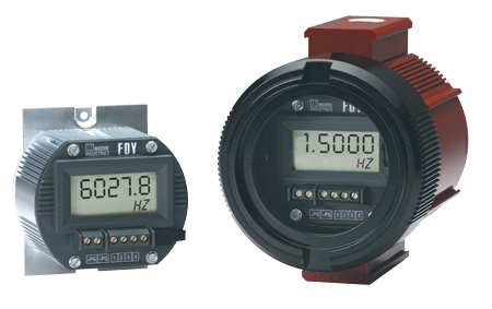 Q: I would like to use either FDY/PRG/4-20MA/12-42DC [HPDN] or FDY/PRG/4-20MA/12-42DC [BH2NG] and I want to install it in a control panel enclosure rated Type 4X. I need to ensure it is suitable for Class I, Div 2. Which one is the best solution?
A: The FDY/PRG/4-20MA/12-42DC [HPDN] without the BH2NG enclosure is Class I, Div 2 rated. It meets the Div 2 requirements when installed in your Type 4 box. You can download the certificate here.
The FDY/PRG/4-20MA/12-42DC [BH2NG], is an explosion proof transmitter approved for use in Class I, Div 1 hazardous areas. This is the same FDY device except it is housed inside the explosion proof/flameproof BH2NG enclosure. This BH2HG enclosure is also rated Type 4X & IP66 which means that it offers sufficient environmental protection to allow it to also be classified as a Class I, Div 2 or Non-Incendive device. The FDY/PRG/4-20MA/12-30DC/-ISF with the [HPDN] housing designation or enclosed in a BH type housing carries intrinsically-safe approvals.
Download the FDY datasheet.
Do you want more information? Download the data sheet. Or visit the catalog.
Need to get price or availability or have a technical question?
Send us a message using E-Help.
Q. I have a temperature application that requires a 12-inch thermowell which can withstand a high temperature of 2,000°F. Most of what we have been using becomes brittle and breaks off at the tip. What would you suggest we use, and what type of sensors do you have that will work for us?
A. We have several different types of metals we can suggest with maximum temperatures up to 2,160°F. Materials that will work well for the thermowell in your application are SS446, SS310, and Inconel 600.
For the sensor type, we recommend a thermocouple Type “K” with Inconel 600 material for the sheath. Also, using 2-inches of thermal-lagging for the thermowell will reduce heat going into the head.
If possible, remote mount the temperature transmitter away from the process connection. Even though Moore Industries temperature transmitters are rated up to 185°F, it could get too hot inside the head if it were mounted directly on top of the process. If you must mount the transmitter near the process connection, we suggest using a stainless steel housing and a ceramic terminal block to terminate the sensor at the process.
Do you want more information? Download the data sheet. Or visit the catalog.
Need to get price or availability or have a technical question?
Send us a message using E-Help.
 Q: We have an R-BOX in a Class 1 Div 2 location with a 120VAC instrument inside. Is this enclosure rated for this atmosphere? It does not appear to have a very good seal for this environment.
A: The R-BOX was designed to meet a Type 4X and IP66 rating, which is suitable for housing a Div 2 approved device. The hazardous area protection is provided by the non-incendive nature of the Div 2 rated device mounted inside. The enclosure simply needs to provide protection from the ambient elements or other flying conductive material.
Learn more by downloading the R-BOX datasheet.
Do you want more information? Download the data sheet. Or visit the catalog.
Need to get price or availability or have a technical question?
Send us a message using E-Help.
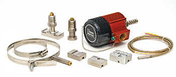 Q. We want to measure bearing temperature in our motors to alert us of overheating. We have used a type of sensor which inserts into the side of the motor, but they leak and fail often. We would like to put something on the surface of the motor outside of the bearing housing, but we do not want something welded to the housing. What can you suggest?
A. The best solution for your application is a WORM sensor with a Magnetic Pad (-MPAD). The -MPAD has 40lbs of attraction and will hold up to a vibrating surface. We also suggest adding our 30G option to the RTD, in order to protect the RTD element inside the sheath from high vibration during motor operation. Standard fixed length sensors cannot withstand this vibration over time. The -MPAD with WORM sensor is easy to install on any ferrous metal surface.
Download the RTI-3 datasheet for more information.
Do you want more information? Download the data sheet. Or visit the catalog.
Need to get price or availability or have a technical question?
Send us a message using E-Help.
Q: I am evaluating the SIX 2-wire Signal Isolator and Converter. Is this device auto-calibrated or will we need to calibrate it ourselves? Does it require two separate power supplies? The specs state that the output is loop powered but I am not clear on the input. Also, is it a problem if we supply both the input and output with the same power source? In our case, it would be the 53.5VDC power supply in the loop currently. We would need to run a parallel path. The input is intended to be a 4-20mA.
A: The SIX is provided pre-calibrated from the factory for the input and output indicated in the model number. The device has potentiometers accessible on the front panel for making adjustments to the zero and span.
The SIX derives its operating power from the voltage that is applied to its output. It consumes 12V of the available voltage applied to its output. The SIX accepts a voltage or current input. If the input is 4-20mA, then the SIX will add 50 ohms of impedance to that loop.
Regarding supplying both the input and output with the same power source, the primary purpose of the SIX is to provide input to output galvanic isolation. Using the same power supply for both would defeat that isolation.
Do you want more information? Download the data sheet. Or visit the catalog.
Need to get price or availability or have a technical question?
Send us a message using E-Help.
Q: We have been using your SPA series temperature transmitters in our hydroelectric power plants with excellent results. These devices have high protection against electromagnetic interference. We would like to purchase temperature transmitters for head mounting and rail mounting that have the same high level of isolation and protection against electromagnetic interference. The sensors are 10 Ohm Cu three wire RTDs and they represent the temperature of generator windings in the hydroelectric power plant.
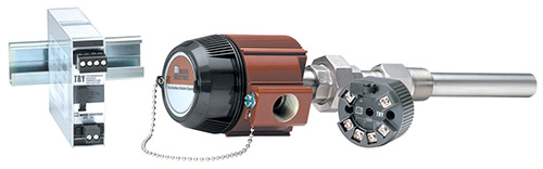
A: Model SPA/TPRG/2PRG/U/-AO [DIN] provides 0.25 mA RTD excitation current. If it is performing well then our PC configurable temperature transmitters, which have the same excitation current, should also perform well. In that case we recommend the TRY series. The head mount style is model TRY/PRG/4-20MA/10-42DC [LH2NS]
If your SPA has the SP2 option instead (Model SPA/TPRG/2PRG/U/-AO-SP2 [DIN] ), that option provides 5mA of excitation current to the 10 ohm RTD instead of the usual 0.25mA. This ensures that a robust input signal from the RTD to the SPA resists interference from the generator’s very strong electro-magnetic fields.
The choices available for a head mounted transmitter with similarly high current RTD excitation are limited. Bear in mind that the objective when designing RTD temperature transmitters is to reduce the excitation current as much as possible to minimize self-heating of the RTD, thereby maximizing the measurement accuracy.
Also due to the reduced power budget of loop powered transmitters there isn’t sufficient power available for the 5mA excitation current of the SP2 option.
A possible solution is one of our older analog loop powered transmitters, the RBX series, which has a relatively high excitation current of 1mA. The RBX, however, is a strictly analog design and must be specified according to the intended resistance range instead of temperature span. For example, for 10 ohm Cu and 0-200 deg C, the resistance is 9.035 to 16.776 ohms. The span is 7.741 ohms. The 7.741 span falls within the 3W5-10 input range.
The head mounted model number is: RBX/3W5-10/4-20MA/12-42DC/-EZ9 [BH2NS].
Do you want more information? Download the data sheet. Or visit the catalog.
Need to get price or availability or have a technical question?
Send us a message using E-Help.
Q: I need confirmation that the THZ2 is a functional like-for-like replacement for the THZ and that basically it will perform the same.
A: With the exception of the THZ/PRG/4-20MA/12-42DC [DH2NG], which has an integral display, the THZ2 has all of the functions of the THZ and the same form and fit.
However, we suggest you consider the newer THZ3, since the THZ2 is being phased out (although it will continue to be available while supplies last). The THZ3 has all of the functions of the THZ2 and the same form and fit. The THZ3 offers additional functionality over the THZ2, can accept two sensor inputs, and utilizes PACTware for PC configuration in addition to HART programmability.
Other features found in the THZ3 that are not included in the THZ are:
- Backup and Fail-Over Protection allows either of the sensors or inputs to be designated as the primary measurement, with the secondary input acting as the backup sensor in case of primary sensor failure.
- Average and Differential Measurement allows you to average the two input measurements or select the differential (A-B or B-A) or absolute differential between the two inputs.
- High-Select and Low-Select Feature enables the transmitter to continuously monitor two separate inputs and designate either the highest or lowest input to represent the analog output.
- Dynamic Variable Mapping permits the user to assign either input or the calculated result of inputs to any of the four HART variables (PV, SV, TV or QV) that can be read by any HART compatible host system.
- Smart Range Alarms offer four HART alarms set to any input or calculated input that detect when the variable is within or outside user preset limits.
- High Availability Option enables the user to select how the AO behaves when there is an input failure or out-of-range value detected by the transmitter. This prevents nuisance alarms on startups or batch process shutdowns.
Download the THZ3 data sheet.
Do you want more information? Download the data sheet. Or visit the catalog.
Need to get price or availability or have a technical question?
Send us a message using E-Help.
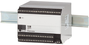 Q: You have a product called HART Interface Module that will pull the 2nd, 3rd and 4th HART variables from a smart HART transmitter and create one 4-20mA signal for each. Do you have or know of an instrument that will take three 4-20mA signals into it and place themdin on one 4-20mA signal as the 2nd, 3rd and 4th variable? I would like to read three transmitters on one 4-20mA signal by reading the variables on my DCS System.
A: We have three products that can take multiple analog inputs and provide that signal data in the form of HART protocol. Those products are the TCM and THZ3 / TDZ3, which are temperature input devices that can take a 4-20mA input across a resistor (shunt) as a mV input.
The TCM is a 16-channel temperature input module that can be polled by a HART master using a device-specific HART command. This HART command retrieves all 16 channels of PV data in one HART message packet.
The THZ3 Dual Input Smart HART DIN-Rail or Field Mount Temperature transmitter can accept two (but not three) 4-20mA signals and write them to two of the HART dynamic variables riding on the analog 4-20mA output signal.
The TDZ3 has the same functionality as the THZ3 but includes a display and can be field mounted in hazardous or non-hazardous areas or mounted on DIN-Rail.
Do you want more information? Download the data sheet. Or visit the catalog.
Need to get price or availability or have a technical question?
Send us a message using E-Help.
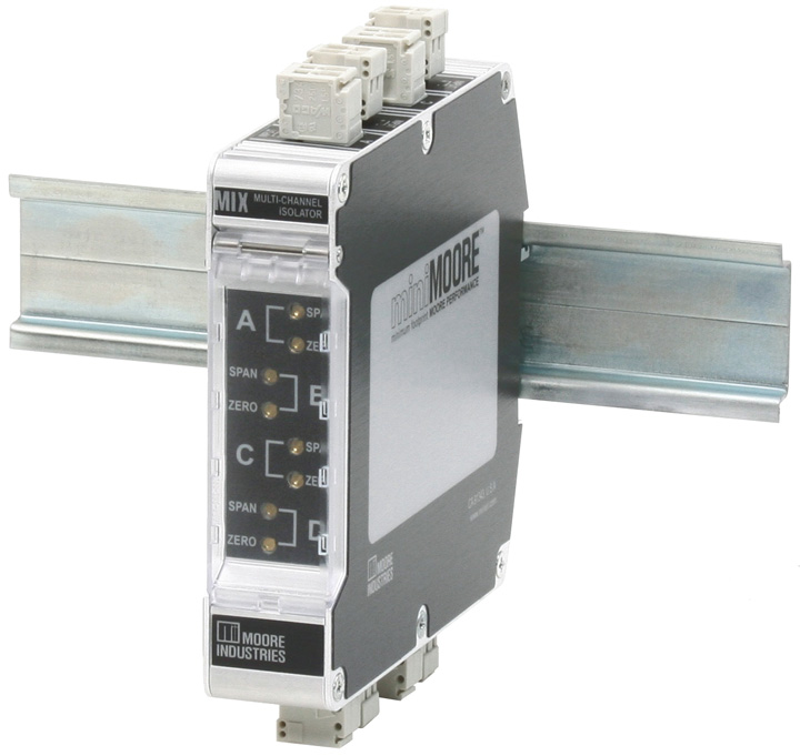 Q: I am looking to take a signal from an analyzer and send the analog output signal to four different locations. Do you have a product that can help me with this?
A: We offer a 4-channel output loop powered isolator and a line powered single input to dual output isolator.
If the receivers at the four locations can supply loop voltage to their respective 4-20mA inputs, then the 4-channel output loop powered MIX isolator (Model: MIX/4X4-20MA/4X4-20MA/12-42DC [DIN]) will work. Wire your 4-20mA signal in series to the four inputs of the MIX.
If the receivers at the four locations have passive (sinking) 4-20mA inputs, then you can either use two of the line powered ECT splitters or two of the dual channel MIT isolators (Models: ECT/4-20MA/2X420MA/117AC/-TX [DIN] or MIT / 2XPRG / 2X4-20mA / U [DIN]). Wire your 4-20mA signal in series to the inputs of the two ECT/MITs.
Do you want more information? Download the data sheet. Or visit the catalog.
Need to get price or availability or have a technical question?
Send us a message using E-Help.
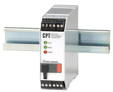 Q: I want to replace a THZ Temperature Transmitter (Model THZ/PRG/4-20MA/12-42DC [DIN]) with a CPT PC-Programmable Temperature Transmitter (Model CPT/TPRG/0-20MA/117AC/-C-RF [DIN]). The THZ unit we are replacing gets its power from the 4-20mA current loop while the CPT unit is going to be powered by 120Vac. Does the CPT need to be specified as "source" or "sink" to work as a drop-in replacement for the THZ unit?
A: The default version of the CPT provides voltage on its output (source). If you would like the output to be passive so it can be wired to an active (voltage supplied) input, specify the "-SINK" option. The CPT will still require 120Vac power on the power terminals.
Note that the newer two-wire output loop powered THZ3 Dual Input Smart HART Temperature Transmitter (Model THZ3/PRG/4-20MA/12-42DC [DIN]) is now available.
Q: My concern is that we will damage the unit or the equipment it is connected to it if we specify the wrong type of output. This unit will be connected to an Allen Bradley 4-20mA analog input module. The previous THZ device got its power from the analog input module so I believe the correct specification would be "sink" for the CPT. Is this correct? Also, can the "source" or "sink" option be changed in the field or does this have to be set at the factory?
A: You are correct that you will need to choose the "-SINK" option on the CPT. The choice of "source" or "sink" for the CPT must be specified in the model number and supplied from the factory that way. It cannot be field changed. Your complete model number for this application would be: CPT/TPRG/0-20MA/117AC/-C-RF-SINK [DIN]. Note that you have also selected an auxiliary alarm contact and enhanced RFI/EMI protection.
Do you want more information? Download the data sheet. Or visit the catalog.
Need to get price or availability or have a technical question?
Send us a message using E-Help.
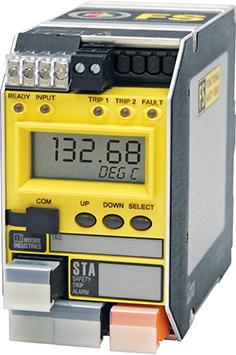 Q: I need to use the STA Safety Trip Alarm in a hardwired panel. Is it possible to configure two different levels of alarm for each of two relays in the STA, in order to have two different trips (one for each relay)?
A: Only one set point can be assigned to each alarm relay of the STA. However the dead-band is adjustable from 0% to 100% of the input span. Therefore you can specify one signal level at which the relay engages and another for when it disengages. If your input signal is 4-20mA, you can connect it in series to the inputs of two STAs in order to obtain 4 independent relay/setpoints.
Q: To clarify my situation: if I have a 0 to 100 bar transmitter, can I trigger Relay 1 at 25 bar and Relay 2 at 75 bar? We need to do this in order to shut down two different pieces of equipment at these pressure levels.
A: This is a typical function of the STA. One relay setpoint is often used for a warning at one level while the second relay setpoint is used for shutdown at the next level.
Do you want more information? Download the data sheet. Or visit the catalog.
Need to get price or availability or have a technical question?
Send us a message using E-Help.
Q: We are in need of a signal converter that converts a 4-20mA logarithmic signal into a 4-20mA linear signal. We need one input and one output per device. Do any of your devices perform this function?
A: We offer several models of signal converters which have look-up table linearization/characterization capability.
The SIY is an output loop-powered unit that can be configured for up to 85 ordered pairs. With this model, each ordered pair must be keyed in using the provided configuration software.
The CPT is a line-powered model that can be configured for up to 128 ordered pairs. The ordered pairs are computed with a spreadsheet, saved as a two column CSV file and then loaded into the provided configuration software. The configuration is then loaded into the CPT.
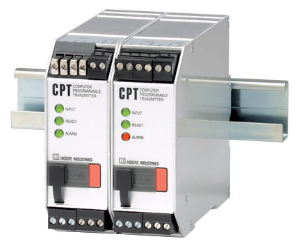 With both models you specify the X and Y values so you can cluster points at the most non-linear part of your table.
Do you want more information? Download the data sheet. Or visit the catalog.
Need to get price or availability or have a technical question?
Send us a message using E-Help.
Q: We are a boiler/burner company dealing with a rising amount of computer-based burner controls. We have installed several and have some blowers that are controlled by VFDs (Variable Frequency Drives). We have run into issues with noise on certain systems. We get occasional problems with 4-20mA feedback from the VFD despite going through the proper grounding techniques. We are wondering if installing an opto isolator on the feedback loop might eliminate our issue. We have used the SIX Signal Isolator many times on the signal going to the VFD to offset impedance issues on the VFD. Can we put an opto isolator on both signals?
A: Whether the SIX or another isolator will cure your problem depends on the nature of the noise and how the loop is energized. Sometimes you can install an isolator without additional analysis and see if it works.
If you have data about the noise, compare it to the noise rejection specification of the isolator. For example, the Common Mode Rejection for the ECT-DIN Signal Isolator exceeds 95dB @ 60Hz with a limit of 1500 Vrms.
When selecting the appropriate isolator, take into account which device is providing the loop voltage on the input and output sides. Per the ECT datasheet, you can see that it is available as an output loop powered, input loop powered or line powered device.
Do you want more information? Download the data sheet. Or visit the catalog.
Need to get price or availability or have a technical question?
Send us a message using E-Help.
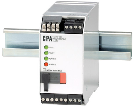 Q: I am looking for a device to create a temperature switch. I currently use a simple temperature switch with a 230°F setting, but at times the temperature of the unit goes over 400°F briefly and destroys the switch. I need to be able to hook a thermocouple up to the device and program a setpoint (with no display required) and have a set of dry contacts open when the temperature rises above the setpoint.
A: Our model CPA PC-Programmable Alarm can accept a thermocouple or RTD input and trip a relay based on the setpoint that you have configured. It can be configured using our software and a USB cable.
Do you want more information? Download the data sheet. Or visit the catalog.
Need to get price or availability or have a technical question?
Send us a message using E-Help.
Q. We would like to use the ECA-DIN in a seismic application. In a worst case scenario of an earthquake, the ECA-DIN must retain its position. We are concerned about the robustness of DIN rail mounting. Is the ECA available with a bolt down option?
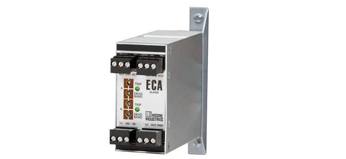
A. We can supply the ECA with side flanges for more robust gearplate mounting instead of the usual DIN rail mounting.
Do you want more information? Download the data sheet. Or visit the catalog.
Need to get price or availability or have a technical question?
Send us a message using E-Help.
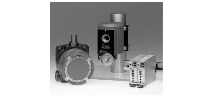
Moore Industries’ family of pressure-to-current transmitters provide an economical solution when a pneumatic device must interface with a data acquisition control system, controller, recorder, or another electronic instrument.
These compact, yet powerful units accept a pneumatic signal (3-15 psig, 0.2-1 bar, 3-27 psig, etc.) and accurately convert it to a proportional 4-20mA (or 10-50mA) output.
Our complete line of P/I transmitters includes models perfect for both control room and field mounting. Moore Industries’ P/I transmitters are available with a wide variety of housings, and with special features and options.
Features include:
- Immune to shock, vibration and position. Perform with exceptional accuracy (±0.2% of span) even in unstable environments
- Mount in any position without performance loss
- Long, trouble-free service life
- Self-sealing pneumatic connection
Do you want more information? Download the data sheet. Or visit the catalog.
Need to get price or availability or have a technical question?
Send us a message using E-Help.

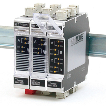 Featuring a very narrow installation footprint, miniMOORE™ Signal Isolators, Converters, Boosters and Splitters combine multiple analog signal channels in a rugged, easy-to-install signal conditioner. Reliable and very economical, the miniMOORE multi-channel family includes the model MIX 2-wire (loop) and the model MIT 4-wire (line/mains) powered models. The complete family delivers cost-effective solutions for an expansive range of signal interface applications.
Features include:
- High-density, 2- and 4-channel configurations
- Switch-selectable current/voltage inputs. The 2-channel miniMOORE models provide DIP switches for selecting input types of 4-20mA, 0-5V, 1-5V or 0-10V for each channel
- 2-wire (loop) and 4-wire (line/mains) powered
- Superior signal isolation
- Universal AC/DC power input
- RFI/EMI Protection
Visit the MIX / MIT product page.
Do you want more information? Download the data sheet. Or visit the catalog.
Need to get price or availability or have a technical question?
Send us a message using E-Help.

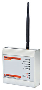 The WNM is a bi-directional, spread spectrum radio modem that delivers the flexibility and cost-saving advantages of wireless data transmission. It is ideal for use with Moore Industries’ NET Concentrator System® (NCS), as well as other SCADA and distributed I/O systems. The WNM is a bi-directional, spread spectrum radio modem that delivers the flexibility and cost-saving advantages of wireless data transmission. It is ideal for use with Moore Industries’ NET Concentrator System® (NCS), as well as other SCADA and distributed I/O systems.
The WNM employs Spread Spectrum Frequency Hopping technology, 128-bit AES (Advanced Encryption Standard) encryption, 32-bit CRC (Cyclic Redundancy Check) error detection, and ARQ (Automatic Resend Query) to provide robust and secure communications. The Spectrum Frequency Hopping technique ensures reliable, noise and interference immune, license-free wireless communications.
Features Include:
- Standard Operating Frequencies - Available models operate at frequency ranges of 902-928MHz or 2.4-2.4835GHz (RF ranges and power factory configured per country)
- Long-Distance Data Transmission - The 902-928MHz units can transmit up to 30 miles(48km); 2.4-2.4835GHz units provide up to 15 miles (24km) transmission range. WNM modules configured as repeaters allow for virtually unlimited transmission range
- Supports Ethernet and Serial Communications
- Plug-and-Play Installation and Operation
- No Regulatory License Required
Visit the WNM product page for more information.
Do you want more information? Download the data sheet. Or visit the catalog.
Need to get price or availability or have a technical question?
Send us a message using E-Help.

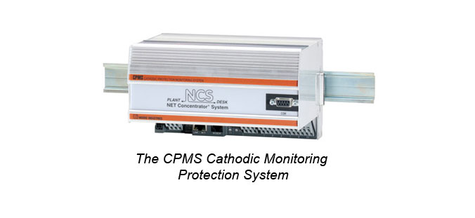 The CPMS Cathodic Protection Monitoring System monitors above and below ground impressed current cathodic protection systems to ensure that proper corrosion protection is in place and operating at the right levels. The CPMS Cathodic Protection Monitoring System monitors above and below ground impressed current cathodic protection systems to ensure that proper corrosion protection is in place and operating at the right levels.
Part of Moore Industries’ NET Concentrator System® family of intelligent distributed I/O, the CPMS monitors the critical current and voltage levels of one or two transformer rectifi ers used in cathodic protection systems. Each module provides four or eight, fully-isolated analog input channels and four discrete (contact closure) inputs. It “concentrates” this data onto one or multiple communication links, and transmits it long distances back to one or more host DCS, PLC or PC-based control systems.
The CPMS accepts up to four discrete (contact closure) inputs from the monitored system. Using an internal control engine, the CPMS can be programmed with internal set points that relate to normal operating conditions within the cathodic protection system. Should monitored parameters go outside of selected limits, or if power to the cathodic protection system is lost, the CPMS alerts of the unwanted conditions at the control system over the data link.
In addition to operating in a stand-alone mode, the CPMS integrates with any of Moore Industries’ NET Concentrator System’s analog, temperature, discrete and relay I/O modules. When coupled with the ROM (Relay Output Module), relay outputs can control rectifiers using accurate GPS time to facilitate taking cathodic protection reference electrode readings.
Features Include:
- Simultaneous dual MODBUS RTU and Ethernet communications
- MODBUS RTU master capability
- Installs in harsh environments
- Quick and simple programming
- Data logger with battery back-up
- Advanced control and math capabilities
- GPS Time feature
Visit the CPMS product page. Download the CPMS data sheet.
Need to get price or availability or have a technical question?
Send us a message using E-Help.
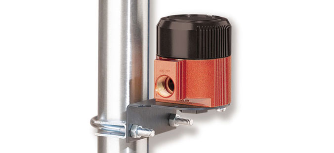 Moore Industries’ durable PIH Pressure-to-Current Transmitter provides an economical solution for any process that requires a rugged instrument capable of interfacing a pneumatic device with a data acquisition/control system, controller, recorder, or other electronic instruments. Moore Industries’ durable PIH Pressure-to-Current Transmitter provides an economical solution for any process that requires a rugged instrument capable of interfacing a pneumatic device with a data acquisition/control system, controller, recorder, or other electronic instruments.
This compact yet powerful unit accepts most pneumatic signals (3-15 psig, 0.2-1 bar, 3-27 psig, etc.) and accurately converts them to a proportional 4-20mA output. The PIH is perfect for field mounting. Its metal casing makes it a tough field-mount unit when you need strength without the added expense of an explosion-proof enclosure.
Features Include:
- Perfect for harsh field environments
- Saves installation costs
- Immune to shock, vibration, and proportional
- RFI/EMI protectionReverse Output Option
- Visit the product page & download the PIH data sheet.
Need to know more about a product, price or availability? Check out the PIH Pressure-to-Current Transmitter
Do you want more information? Download the data sheet. Or visit the catalog.
Need to get price or availability or have a technical question?
Send us a message using E-Help.

 Timely knowledge about your process enables better decisions and faster preventive action. Now you can get the process detail that you need from your Smart HART devices to MODBUS/TCP and HART-IP based monitoring and control systems at the speed of Ethernet with the HES HART to Ethernet Gateway System from Moore Industries.
Connect up to 64 Smart HART devices to the HES and collect the Dynamic Variables and the Device Variables, along with diagnostic bits and bytes, from each device that helps deliver critical information needed to help you address process and device problems before they turn into unplanned downtime.
Whether you need data from one device or many, the HES meets your need with a single channel and four channel configurations. The single channel configuration supports up to 16 HART devices in digital multidrop mode, or it can support one device in a standard point-to-point 4-20mA loop configuration. The four channel configuration can support up to 64 total HART devices for high-density installations.
The HES supports HART field devices both old and new with HART 5, 6 and 7 revisions, including devices such as Coriolis, magnetic, vortex, ultrasonic and multivariable mass flowmeters along with pressure, pH, level, temperature transmitters, and even smart valve positioners. Its robust memory capacity can handle thousands of process variable and diagnostic data points from connected smart HART devices.
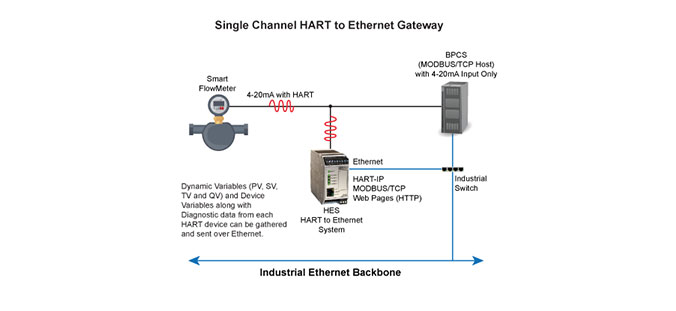
The HES is simple to configure over Ethernet using PACTware or other FDT compliant host with supplied HES DTM. Easy-to-use menus give you the ability to fully configure the HES including HART channel communications, MODBUS communication, and mapping settings and network security parameters.
You can view all of the HART data from connected field devices in read-only mode with any web browser via the HES’ built-in web server or a MODBUS/TCP compliant host. The HES also supports HART-IP, which allows you to monitor any of the connected HART device variables, HES variables, or diagnostics. Support for these open industrial protocols enables interface with any process control or asset management system while taking advantage of any Industrial Internet of Things (IIoT) initiatives that facilitate the propagation of process data to higher level corporate or analytical systems.
The new HES continues the Moore Industries reputation for rugged and reliable products that are designed and built to perform dependably year after year.
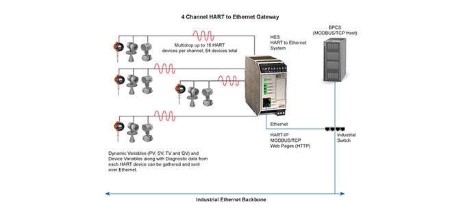
Demand Moore Reliability
Do you want more information? Download the data sheet. Or visit the catalog.
Need to get price or availability or have a technical question?
Send us a message using E-Help.

An overpressure situation in pipes is dangerous and can lead to significant damages to property, pipe ruptures and even injuries and death. Having a system in place to prevent an overpressure situation is critical and one way to accomplish this is with a High Integrity Pressure Protection System (HIPPS).
 A HIPPS provides a barrier between high pressure and low-pressure parts of an installation to prevent the release of fluid or gas into or otherwise contaminate the environment. An example of a HIPPS is an offshore well platform where the subsea oil or gas lines can occasionally present a harmful pressure surge in the pipeline. The HIPPS is designed to shut off the source before the design pressure of the downstream process is exceeded, avoiding a rupture of a line or vessel.
A HIPPS consists of three main components:
•Pressure transmitters
•Logic solvers
•Fast-acting shutoff valves
Many people assume that the logic solver has to be a safety PLC. But in many cases, a discrete logic device for each loop, which avoids the complications and expense of a programmable solution, is a sensible option. The “Logic Solvers for Overpressure Protection” white paper shows how discrete logic devices such as the STA Safety Trip Alarm are suitable for use while providing a flexible, low-cost and user-friendly solution.
While the safety PLC approach offers advantages for installations where there are a high number of field I/O safety loops, many plants have few such loops. For these plants, discrete logic solutions offer several advantages including creating a simple architecture, reducing cabling costs and avoiding the development cost of application programming.
The STA is easy to install with its wide range of power supply options and its small package that helps to keep it separate from non-safety instrumentation. In the event of maintenance due to transients or failure, it can be readily swapped out at a low unit and operational cost without interfering with the other processes in the plant. Local indication gives reassurance that the status of safety loops is reported directly.
The “Logic Solvers for Overpressure Protection” white paper shows safety engineers the steps needed to determine the right logic solver for their SIS. It shows the methodology and calculations for determining the applicability of logic solvers in SIL 1 and SIL 2 environments. It includes examples of system topologies and their associated Safety Integrity Level (SIL) calculations.
The STA Safety Trip Alarm is part of Moore Industries’ FS Functional Safety Series of instruments. Each of these instruments is designed and built in compliance with IEC 61508, the leading worldwide functional safety standard, and certified by exida for use in a Safety Instrumented System. In addition to our FS Series of products FMEDA (Failure Modes Effects and Diagnostic Analysis) reports available on many of our products that are used in safety applications.
Find out more information about these products at the FS Functional Safety Series section of our website. You can also download the related “Logic Solvers for Tank Overfill Protection” white paper.
Q: We have an existing Rosemount 1151DP tied to a Provox DCS. We also have a Moore Industries DDA 4-Wire Current and Voltage Alarm in the system to provide a Flow Switch Low and Flow Switch High interlock to our gas supply valves. Will newer products from Moore Industries provide more – or better – protection than the DDA?
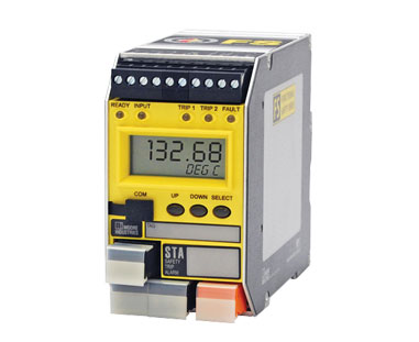
A: The STA Safety Trip Alarm and SPA2 Site Programmable Alarm have alarm functions and can be used instead of the DDA. Both products have FMEDA reports which define the Probability of Failure on Demand and can provide a better degree of protection than the DDA. Additionally, the HIM HART Interface Module has alarming functionality that could also be used with the 1151DP transmitter.
The STA monitors the analog signal and is specifically designed for IEC 61508 applications. It is approved by exida for use in Safety Instrumented Systems (SIS) up to SIL 2 and in redundant architectures (1oo2, 2oo3, etc.) up to SIL 3.
Like the STA, the SPA2 can also monitor the analog signal and provides up to four alarms, a display, and an optional 4-20mA retransmission. The SPA2 is our most popular alarm choice for loops that are not specifically designed in accordance with IEC 61508/61511The HIM monitors the digital component of a HART signal and can be specified with up to two optional relay outputs, which can be configured for signal level alarms or for a number of HART status bits. It can be used to provide diagnostic coverage for a HART transmitter since it monitors the transmitter’s status bits.
Do you want more information? Look up a data sheet to download. Or visit the catalog.
Need to get price or availability or have a technical question?
Send us a message using E-Help.
Moore Industries is continually updating our website with new datasheets, user’s manuals, CAD drawings, configuration software and other materials.
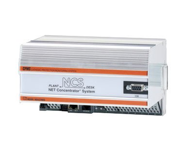
Remember that our website is the definitive place to find the most up-to-date product information, so please check here when you need something.
Among the new files currently available on the website is an update to the CPMS Cathodic Protection Monitoring System datasheet to reflect the new GPS Time option. This is an optional method for keeping accurate time when an SNTP (Simple Network Time Protocol) network is not available.
Here are some of the files that have recently been updated on our website:
Datasheets:
CAD Drawings:
Other:
Do you want more information? Download the data sheet. Or visit the catalog.
Need to get price or availability or have a technical question?
Send us a message using E-Help.

Q: I need a 4-wire isolator and want to see if your MIT Multi-Channel Signal Isolator will work in my application. I have several 4-wire transmitters where I need to split and isolate the output signal to receivers that are passive (not powered). Will the MIT work provided that I supply 24Vdc power to the unit?
A: The MIT appears to be a perfect fit for your application. MIT’s input is passive, so it is compatible with the active output of a 4-wire transmitter. Because its outputs are active, they are compatible with the passive inputs of the receiver devices. In addition, it uses a universal power input, so it will accept 24Vdc power.
Do you want more information? Download the data sheet. Or visit the catalog.
Need to get price or availability or have a technical question?
Send us a message using E-Help.
State regulations required a major pulp and paper company to monitor and record daily effluent water rates. This requirement was being fulfilled by sending an employee from their main control site to a remotely located pond three times a day to manually record water levels. This process was inefficient, time-consuming and didn’t provide them with real-time data.
By installing a system utilizing technology from Moore Industries, the pulp and paper company implemented a system that is scalable for future installations while reducing employee workload and maintaining state regulatory compliance. This process is detailed in a white paper available for download on our website. It highlights how the use of the HCS HART Concentrator System and the NCS NET Concentrator System were critical in helping the company efficiently comply with government regulations.
HART flow level measurements at the pond site were converted to MODBUS RTU by a HCS and sent from a WNM Wireless Network Module at the pond to a receiver radio at the boiler control room. The information was relayed from the wireless radio to an HMI display and DCS/Historian by the NCS. This system enables the company to efficiently get accurate and required readings on the levels in their effluent water system.
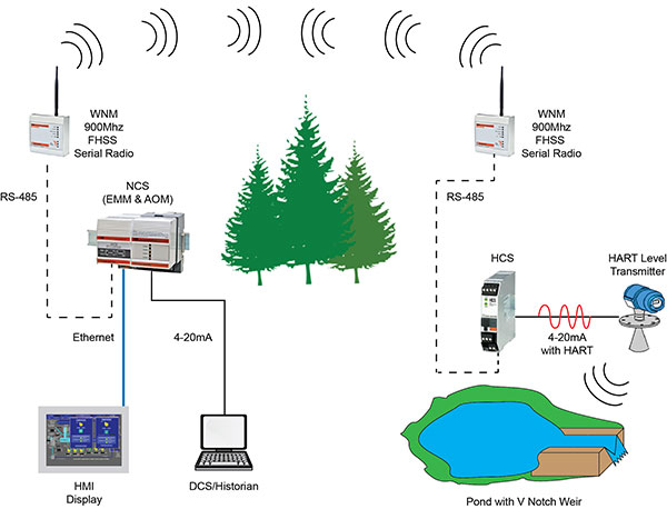
Do you want more information? Download the data sheet. Or visit the catalog.
Need to get price or availability or have a technical question?
Send us a message using E-Help.

WNIPT: Extracting HART Data from Smart Instruments
According to the FieldComm Group (formerly the HART Communications Foundation), there are more than 30 million HART-enabled instruments installed in chemical and process plants worldwide, and most process transmitters made today are HART compatible. The HART digital signal often contains valuable process measurements and other variables including instrument status, diagnostic data, alarms, calibration values and alert messages.
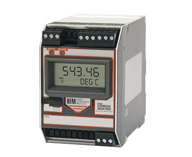
However, many systems fail to utilize the critical information available from HART-enabled transmitters, valve positioners, flowmeters and other "smart" devices. The February 2015 issue of the Australian magazine What’s New in Process Technology features an article from Moore Industries addressing these concerns. “Extracting HART Data from Smart Instruments” shows how a HART interface device such as our HIM HART Interface Module makes acquiring HART data simple. The data can be sent to a control system via analog signals, discrete outputs or serial communications.
Control Design: Process Skid Standardization
Another recent article highlighting Moore Industries was published by Control Design. In “Process Skid Standardization: What Manufacturers Want,” Dan Herbert discussed an issue common to OEM process skid builders. They keep their costs down when they can deliver the same product to as many customers as possible without customization. However, their clients often have specific needs that they want to be addressed by their process skid.
The article includes feedback by Moore Industries Senior Applications Engineer Jim McConahay, PE, who discussed how our NCS NET Concentrator System can serve as a universal MODBUS I/O interface and eliminate the need for most process skid custom interfaces.
Keep up-to-date with our media coverage at our website.
Check out our HART Gateways, Monitors and Interfaces.
Need to get price or availability or have a technical question?
Send us a message using E-Help.

For many temperature applications, getting a high level of accuracy is vital. A white paper from Moore Industries highlights how plant and site engineers can ensure the most accurate temperature measurement for critical applications. Available for download from the Moore Industries website, “A Practical Guide to Improving Temperature Measurement Accuracy” details steps that can also help end users improve the stability of their measurements and reduce calibration costs.

“A Practical Guide to Improving Temperature Measurement Accuracy” shows how to select the best sensor for a particular application and ways to improve the accuracy of the sensor you choose. In particular, it details the reasons why 4-wire RTD sensors are almost always the best choice for high-accuracy temperature applications. Using 4-wire RTD sensors eliminates the errors caused by a copper lead wire. The paper also explains the relationship between classes of sensors (such as Standard and Premium Grade thermocouples and Class A RTDs) and their error rates.
Along with learning how to select sensors, the paper also covers how to reduce errors caused by plant noise, using bath calibration to minimize RTD measurement errors and the relationship between remote I/O and temperature accuracy.
The white paper is written by National Sales Manager Gary Prentice, who graduated with a degree in Electrical Engineering from Lafayette College in Pennsylvania and has 36 years of experience working in the process control industry. He has encountered almost every possible temperature application over his career and is the perfect person to explain the benefits of using 4-wire RTDs.
You can get watch a tutorial on this topic by viewing a Webinar that Gary did a few months ago, which gives even more specific examples of how to improve the accuracy of your temperature measurements.
Moore Industries rep Soltex Chile S.A. recently exhibited at the Exponor 2015 show, which takes place every two years and focuses on the mining industry. It was held in Antofagasta, the main city in northern Chile, which is near the country’s world-class mining operations including copper, gold and nitrates. It’s an important show with plenty of opportunities to connect mining companies with instrumentation solutions.
Soltex’s booth at the show included Fieldbus Device Couplers and Power Supplies from MooreHawke, a division of Moore Industries. These products help to maintain and simplify communications between mining operations and control systems – even in hazardous areas. For example, the TRUNKGUARD Series 200 Fieldbus Device Couplers offer multiple benefits for engineers designing FOUNDATION fieldbus H1 and PROFIBUS PA networks:
- Auto Segment Termination: The patented technology prevents fieldbus segment failure from under- or over-termination, a major problem in fieldbus startups. The TRUNKGUARD's auto-termination feature assures that local parts of a fieldbus segment will continue with proper termination even if remote parts of that segment are accidentally disconnected. This prevents costly downtime and hazardous situations
- Short Circuit Protection: On detection of excess current on a fieldbus spur, the TG200 reacts immediately (20 microseconds) to switch spur current to a nominal trickle-level, rather than limiting the fault current to a fixed (and always higher) level as is typically done by competing units. With removal of the short, the spur is automatically reconnected to the fieldbus segment.
- LED Displays: Diagnostic LEDs positively indicate power status on each fieldbus spur, spur short circuits and the status of auto termination.
To learn more about our Fieldbus solutions, please visit the catalog.
How about this for a ThrowBack Thursday post? One of the photos in our archive shows Mr. Moore at the groundbreaking for Moore Industries’ worldwide headquarters more than 40 years ago. Within six months of the groundbreaking, the company’s first employees had packed up their equipment, loaded it into moving vans and brought it overall in the course of one weekend.
 Our building has come a long way from the groundbreaking. Today there are 158 employees here doing everything from manufacturing and engineering new products to handling sales and technical support. A mezzanine was added after the Hawke and Powers acquisitions to address the need for additional manufacturing capacity.
Moore Industries has come a long way in 40 years. Today the company is one of the most recognized and respected names in the world of process instrumentation with millions of units sold and installed in projects all over the world. Part of the reason that Moore Industries has remained so successful is that the company has maintained the same commitment to quality that it had when Mr. Moore founded it in his garage back in 1968. Making sure that customers get solutions to their instrumentation needs is paramount to our philosophy and guides us in the manufacturing and service of our products.
Keep checking in with us for more ThrowBack Thursday posts as we uncover hidden gems from our archive!
Q: I am looking for a differential temperature transmitter. We have used the SPT in the past and know that it will work, but I don’t know if you can use two inputs of two different 4-wire RTDs with the SPT.
A: The SPT has only four input terminals; therefore the number of RTD wires is limited. For differential temperature, one RTD can be a 3-wire and the other RTD can only be a 2-wire. The lead length compensation wire of the 3-wire connection compensates for the lead length of both RTDs. This is only useful if you make sure that all five wires have identical resistance.
To answer your question, you may use two 4-wire RTDs, but you cannot connect all of the wires unless you do it as described above. Wiring details are shown in Figure 17 of the installation manual.
A better option is to use our DIN rail mounted THZ3 HART temperature transmitter, a new model which can accept two three-wire RTDs and provide a differential measurement output. The configuration of the THZ3 is done by utilizing DTMs with PACTware on your PC or by using a HART compatible handheld device or HART host.
Details about the input connections of the THZ3 are in Figure 2.2 of the installation manual.
Model Example: THZ3/PRG/4-20MA/12-42DC [DIN]
Do you want more information? Download the data sheet. Or visit the catalog.
Need to get price or availability or have a technical question?
Send us a message using E-Help.
Want to make sure that you don’t miss any of our blog posts, press releases, product news and other company information?
We’re now giving you more ways than ever before to connect with Moore Industries. You can follow us on multiple different social media sites to make sure that you stay up-to-date with everything that is happening with our company by following us at these social media sites:


 Starting with the THZ3 and TDZ3, Moore Industries introduced a new way for our customers to configure our products.
The transmitters are both HART and DTM (Device Type Manager) programmable, which means they can be easily programmed and interrogated from anywhere at any time on a 4-20mA loop. This can be done with a standard HART handheld communicator, a HART-compatible host or with any FDT (Field Device Tool)-compliant host or program such as PACTware (available for download at our website) utilizing Moore Industries’ DTM.
At its core, the FDT model creates a unified standard for communications that take place between field devices and host systems. The DTM is the specific software component that contains data, functions and logic elements specific to the device. In the case of the THZ3 and TDZ3, the PACTware software is an interface that provides comprehensively advanced programming capability for thorough transmitter configuration.
One of the main benefits for end users of the FDT technology is that it frees them from constraints caused by being tied to a specific platform or communications method when configuring and monitoring devices. They can choose the best product for their installation and know that it can be easily integrated into their system. A single FDT frame application supports multiple communications protocols such as HART, PROFIBUS, FOUNDATION Fieldbus, DeviceNet, Interbus, AS-Interface and PROFINET IO with other protocols soon to follow.
For more information on the advantages of FDT technology, visit the Technology Benefits page of the FDT Group’s website. You can find additional information on Moore Industries' use of PACTware by reading our recent press release on the subject.

Q: I am interested in an ECA alarm unit, model #: ECA/4-20MA/DH1H1/24DC/DIN. I have three questions:
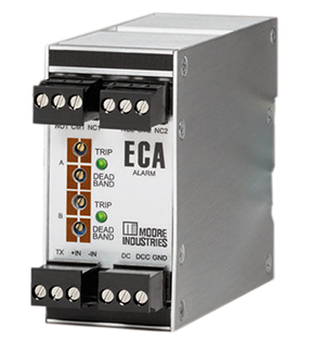
1. I have a need for three different trip setpoints based on the same transmitter input. How can I accomplish this with the ECAs? Can I use two ECAs using the second ECA with a 1-5VDC input or can the 4-20mA signal be run in series through both ECA inputs?
2. Do I need to specify the -RF option to get the RFI protection? And is the testing for both radiated and conducted susceptibility (RS103, CS114, CS115)? Is it possible to see the test report for the EMI/RFI testing?
3. Is DIN-rail the only mounting option?
A: To answer your three questions:
1. Your 4-20mA signal can be connected in series to the inputs of more than one ECA, each of which with a 50 ohm load on the loop. Alternatively, you can use a SPA2 Limit Alarm Trip (Model #: SPA2/HLPRG/4PRG/U [DIN]) which has four setpoint relay outputs.
2. The ECA-DIN has RFI/EMI Protection to 10V/m, 20-1000MHz for which the trip point would not be affected by more than 0.1% of span. It conforms to the following EMC specifications:
EN50081-2, 1993, Generic Emissions Standard, Industrial Environment.
EN50082-2, 1995, Generic Immunity Standard, Industrial Environment.
EN61010-1, 1995, Safety requirements for electrical equipment for measurement and control use.
3. Both the ECA-DIN and the SPA2 are designed for DIN rail mounting; however, we also offer them with options for flange mounting.
Do you want more information? Download the data sheet. Or visit the catalog.
Need to get price or availability or have a technical question?
Send us a message using E-Help.
Control Design recently took a look at the current state of remote I/O. Contributing Editor Hank Hogan suggests that remote I/O is becoming “smaller, faster, customizable and intelligent” thanks to innovations within the industry.
The article highlights several examples of companies who have saved money and increased the functionality of their processes by utilizing remote I/O. In one example, an electrical contractor uses automated PLC systems to control construction, excavation and mining machines. In many cases, the machines at the
construction site were a large distance from the main processor – in some cases up to a mile away. This meant using expensive wiring to span the distance and sending a technician on-site if one of the cables failed.
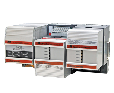 Using remote I/O solves many of these problems. Two locations can be connected via a single twisted wire pair, Ethernet or fiber-optic communication link. Moore Industries offers a wide range of remote I/O solutions including the NCS NET Concentrator System®, which can be used to send just a few – or hundreds – of process signals between the field and a control system whether close by or remote. It’s ideal for creating new monitoring and control networks and also for leaving existing “legacy” sensors, analog instruments and valves in place while taking advantage of digital signal transmission capabilities.
The NCS has several features that make it ideal for plants and remote environments. It offers enhanced RF/EMI protection that eliminates ground loops and protects against the effects of electrical "noise" found in busy plants. It can also be installed in harsh environments with an operating range of -40°C to +85°C (-40°F to +185°F).
For more information about the use of the use of Distributed I/O in plant settings, please download our "Peer-to-Peer Distributed I/O Systems Solve Signal Interface Problems" white paper.
Another option available for connecting field instruments to control systems is to use wireless I/O. This method completely eliminates the need for wiring, makes it easy to expand a network and allows for the transmission of signals across large distances.
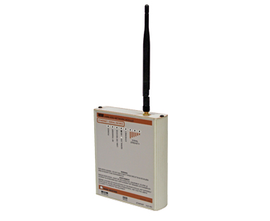 The WNM Wireless Network Module from Moore Industries can be used in conjunction with the NCS to communicate with just one – or multiple – WNM modules configured as Remote modules in a Point-to-Point system. In a Point-to-Multipoint architecture, modules can be configured as repeaters to relay signals when a direct line of sight does not exist between a Master and Remote modules, or to significantly extend the transmission distance allowable within a WNM network.
Find more information about Moore Industries' complete line of remote I/O products by downloading our line card.
Do you want more information? Download the data sheet. Or visit the catalog.
Need to get price or availability or have a technical question?
Send us a message using E-Help.
Q: We have been using Moore Industries DCA series switches for some time. Is there a like-for-like digital microprocessor-based replacement available?
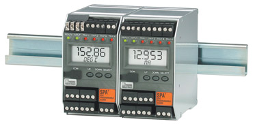
A: The SPA2 series is a microprocessor-based design with all of the capabilities of nearly any permutation of the DCA. It does have a different form and fit, so we will need to know the complete model number of your DCA unit in order to recommend a SPA2 model.
The most common type of DCA mounts to a back panel with four screws, such as model DCA/4-20MA/DH1L1/117AC [UB]. We can provide the SPA2 with the same mounting bracket so that it fits the same footprint and hole pattern.
Do you want more information? Download the data sheet. Or visit the catalog.
Need to get price or availability or have a technical question?
Send us a message using E-Help.
Q: I am monitoring up to 13600 Hz from a magnetic pickup on a gas turbine for speed indication and would like to use the FDY Frequency-to-DC Converter. Are either the PRG input or the 10-250V input handle this frequency?
A: Both input options can handle this frequency.
Normally the PRG input is correct for magnetic pickups. Some of them will put out a pulse voltage above the FDY's max of 30VAC, but it can be lowered by moving the pickup farther from the target. Use the FDY/10-250AC if you know for sure that the voltage pulse will be above the FDY/PRG’s upper limit. However, with this model, the pulse must be at least 10VAC.
Please note that the FDY with the 10-250AC input is not available with I.S. approval.
Do you want more information? Download the data sheet. Or visit the catalog.
Need to get price or availability or have a technical question?
Send us a message using E-Help.
Q: I have a question about the ECA-DIN Current and Voltage Alarm with the DH1L1 (Dual, High/Low, Failsafe) output option. The literature for the product says that "the failsafe relays are de-energized in an alarm condition or during power loss to the unit." Is this statement also true if there is a loss of input signal such as a broken wire?
A: The Failsafe setting means that the relay coils are de-energized in the alarm state. Naturally, if power is lost they will be de-energized. In case of loss of signal, the ECA will perceive the condition as a low signal and behave accordingly. That is, if you have a low alarm setting, the alarm will be activated. If you have a high alarm set, it will not be activated.
If you need more functionality such as being able to discern between a low signal and a lost signal, we recommend the SPA2. Unlike the ECA, it is a microprocessor-based design. This means that it can be configured for a variety of alarm and input signal conditions.
Do you want more information? Download the data sheet. Or visit the catalog.
Need to get price or availability or have a technical question?
Send us a message using E-Help.
We know it is easier for many customers to communicate using MODBUS RTU protocol than HART protocol and that makes the HCS HART® Concentrator System a very popular tool.
We also know customers want more diagnostic information so they can access the health of their processes and instrumentation. HART Command 48 is what the industry and the HCS uses to retrieve diagnostic information from the HART slave device, whether that is a transmitter or a valve positioner. The HCS will not implement Command 48 unless you turn on that feature by checking “Acquire Additional Status” on the HART tab of the configuration software.
Once enabled, if your HCS has firmware version 4 or earlier, the HCS retrieves Status bytes 0 through 5 and populates the diagnostic data into MODBUS registers. With 6 bytes by 8 bits each that is 48 pieces of information. Should you be using one of our newer HCS with firmware version 5 or higher, we pull 25 bytes or 200 bits of diagnostic data and allow it to be read by the MODBUS master.
Of course, the specific diagnostic information is under the control of the manufacturer of the transmitter or positioner, but the HCS makes it easily readable.
Are you or your customers taking advantage of this powerful tool?
Do you want more information? Download the data sheet. Or visit the catalog.
Need to get price or availability or have a technical question?
Send us a message using E-Help.
Last month we told you about a new video tutorial on the configuration of the THZ3 and TDZ3. We’ve now updated our YouTube page with video tutorials from Customer Service Director Bob Croughwell on how to use the included software to configure several of our most popular products:
•STA Safety Trip Alarm (TPRG and HLPRG models)
•SPA2 Limit Alarm Trips (TPRG and HLPRG models)
•HCS HART Concentrator System
There is a video playlist for each product with several videos showing the steps you can take to program and monitor individual features for each product. Along with an overview of the configuration software, some of the feature-specific tutorial videos include information about:
•HART and HART Devices
•MODBUS
•Status
•Alarms
•Analog Inputs/Outputs
•Custom Curves
•Display
•Scaling
Make sure you check out our YouTube page to see the latest tutorials and other informative product videos from Moore Industries.
Do you want more information? Download the data sheet. Or visit the catalog.
Need to get price or availability or have a technical question?
Send us a message using E-Help.

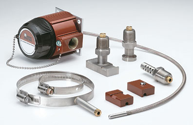
The original goal when creating the WORM Flexible Temperature Sensor was to provide a sensor that could be cut in the field to accommodate various size wells and assemblies. Experience has proven this design helps with other obstacles in the field:
•Dirt, mineral deposits, corrosion scaling and other debris accumulates on the inside of the wells over time.
When you start with a 0.25” O.D. sensor and a 0.26” I.D. well, this added debris makes it very difficult to get sensors in and out of the wells. The WORM has an O.D. of 0.237”, which gives it an advantage to get past the debris to achieve an accurate reading.
•Horizontally-installed wells have a tendency to sag with time and temperature. This means removing and reinserting a rigid sensor can present challenges. The flexible design of the WORM makes installing replacement sensors easier.
•The solid sheath portion of the WORM is only about 1.5” long, which is much shorter than traditional solid sheath sensors. This gives the WORM advantages in applications where measurement speed is critical. The WORM is 30 percent faster than traditional solid sheath sensors, where the long solid sheath serves as a heat sink that sucks heat away from the hot tip of the sensor. The thermal differences have to stabilize before the tip of the long solid sheath can achieve an accurate process temperature reading. That same effect is eliminated in the WORM since the sheath is only 1.5” long and always at the tip of the well.
•With the smaller mass of the WORM sensor, you also gain more durability in high vibration applications versus standard sensors.
•Replacing an old, straight sensor is easy and fast with the WORM sensor. The WORM’s design allows the user to install and replace an older straight sensor by going through the enclosure. During installation, the WORM bends around and through the top or face of the enclosure. It slides through the enclosure’s entry port and snaps into place without removal of the enclosure, rigid conduit, connection head or any assembly components.
Learn more about the WORM by watching our product video
Do you want more information? Download the data sheet. Or visit the catalog.
Need to get price or availability or have a technical question?
Send us a message using E-Help.
Q: We are looking to take an RTD or thermocouple signal input and output it to two 4-20mA outputs. We also could take the same temperature input and output the same signal twice. What are our options?
A: Using our HIM HART Interface Monitor along with a HART temperature transmitter such as the THZ3 is the most accurate solution. The HIM polls the THZ3 via HART and offers up to three separate and isolated analog outputs. Other options include::
A loop-powered TRY temperature transmitter and the ECT-DIN signal splitter. The splitter provides the loop power to the temperature transmitter and receives its signal. It then provides two isolated outputs. The ECT-DIN can be powered with 24DC, 117AC or 230AC.
Models:
•TRY/PRG/4-20MA/10-42DC [DIN]
•ECT/4-20MA/2X4-20MA/117AC/-TX [DIN]
A temperature transmitter such as the CPT and a signal isolator such as the ECT-DIN that are both line-powered. The output of the transmitter is to be connected in series to the input of the isolator and to one of your two loads. The output of the isolator goes to your other load.
Models:
•CPT/TPRG/0-20MA/117AC [DIN]
•ECT/4-20MA/4-20MA/117AC [DIN]
Do you want more information? Download the data sheet. Or visit the catalog.
Need to get price or availability or have a technical question?
Send us a message using E-Help.
Want to see exactly how our SIL 3-capable STA Safety Trip Alarm serves as a logic solver that goes beyond what customers would expect from a standard alarm trip? A video available at our Interface Solution Video Library shows how the STA can initiate emergency shutdown procedures or alert personnel of unsafe process conditions.
The video is hosted by journalist and industry expert Peter Welander and features a demonstration of how the STA serves as a Single Loop Logic Solver in Safety Instrumented Systems (SIS). In the video, the STA monitors a “hot pot” filled with water. When the temperature goes above or below set points, dual alarm outputs on the STA signal a warning that an unsafe state has been reached. The video also shows how a third alarm monitors input or instrument faults such as a failed sensor or input signal.
The STA performs some of the same functions as expensive safety PLCs but is more affordable and easier to program. The process alarm trips and analog outputs are user configurable via front-panel push buttons. Configurations can be downloaded to multiple STA units with a free software utility program. It has been subjected to extensive testing by Exida and is fully compliant to IEC 61508. The STA is approved for single use in Safety Instrumented Systems (SIS) up to SIL 2 and in redundant architectures (1oo2, 2oo3, etc.) up to SIL 3.
Do you want more information? Download the data sheet. Or visit the catalog.
Need to get price or availability or have a technical question?
Send us a message using E-Help.

 The newly-released “Vetting Smart Instruments for the Nuclear Industry” white paper details how Moore Industries has designed and configured key products for nuclear safety-critical applications – particularly in the United Kingdom. Moore Industries’ early experience with the EMPHASIS assessment tool in the UK helped further refine the company’s approach to building products designed for functional safety and use in the global and UK nuclear industry.
Moore Industries worked with the Control and Instrumentation Nuclear Industries Forum (CINIF) in the UK on the conceptual development of the EMPHASIS assessment tool for smart instruments intended for use in nuclear safety-critical applications in the UK. Released in 2005, EMPHASIS provides a common framework for determining the suitability of devices in nuclear industries. Earlier designs for process control and safety systems used “good engineering practices and experience” as guidelines. As functional safety awareness grew and software-based products became more complex, standards such as IEC 61508 evolved to create more comprehensive guidelines for implementing safety.
Moore Industries’ compliance with IEC 61508 significantly contributes toward the EMPHASIS assessment for Production Excellence, one of two “legs” used to substantiate safety to the regulator. The second leg involves Independent Confidence Building Measures – measures and techniques such as Static Analysis or Statistical Testing on a product’s source code to prevent potential systemic failures and also taking into account the application demands of the device to be deployed.
Moore Industries has been assessed against and used the EMPHASIS tool to achieve approval for four smart instruments, with a fifth instrument currently in the approval process. The “Vetting Smart Instruments for the Nuclear Industry” white paper briefly outlines the steps that Moore Industries took to ensure that these products were designed following strict adherence to the IEC 61508 standard and how using the EMPHASIS process allowed the company to improve the design and configure new and existing products for safety in nuclear-related fields.
More information on Moore Industries’ FS Functional Safety Series of products is available at our website.
 Moore Industries makes it easy for you to check out all of our informative videos showcasing the capabilities of our products. You can go to our Interface Solution Video Library and watch our entire library of videos which give a detailed breakdown of specific product features, overviews of product categories and show how our products solve specific applications.
The products featured in the videos include:
•STA SIL2 and SIL3 Capable Safety Trip Alarm
•The WORM Flexible Temperature Sensor
•NCS NET Concentrator System®
•WNM Wireless Network Module
•IPX2 Current-to-Pressure Transmitter
•HCS HART Concentrator System®
•MooreHawke TRUNKSAFE Fault-Tolerant Fieldbus System
Make sure you check back regularly to see the latest videos from Moore Industries.
Controlling electricity costs is a major factor in the management of a manufacturing plant. It’s not uncommon for electrical utilities to charge a premium rate for power used during “peak” periods. If a manufacturing plant knows when these peak hours are, they can schedule major production for other time periods and save a significant amount of money.

Moore Industries helps manufacturing plants monitor peak demand with our PWT Watt Transducer. It can be used to help analyze power usage trends and find out when peak demands occur. Plants can shed non-vital loads during these times and reschedule the work for periods where power costs are lower.
Do you want more information? Download the data sheet. Or visit the catalog.
Need to get price or availability or have a technical question?
Send us a message using E-Help.

 Moore Industries-Belgium recently found success at the M+R 2015 show in Antwerp. The 37th edition of the show had a 12 percent increase in attendees from the previous show and Belgium Sales Manager René Michiels said that representatives from more than 50 companies came by the booth during the show and the leads are already starting to translate to orders.
The Moore Industries-Belgium team always goes out of their way to do big things to attract attention at shows and M+R 2015 was no different. This year they hired a magician to be at the booth and perform sleight-of-hand tricks using special Moore Industries playing cards highlighting our exida certified IEC 61508 Functional Safety instruments. People in the crowd were able to keep the cards after the trick was done. According to René, the illusionist was a big hit and helped to bring some excitement to our booth.
Q: I want to transmit temperature readings from 44 different four-wire RTDs over MODBUS using your TMZ PC-Programmable MODBUS Temperature and Signal Transmitter. Can I use the EMM Ethernet/MODBUS Interface Module of the NCS NET Concentrator System® to concentrate the outputs of the TMZ? I would like to have the EMM configured as a MODBUS RTU Master and the TMZs as MODBUS RTU Slaves and then output from the EMM as a MODBUS/TCP to my control system. Can this all be done?
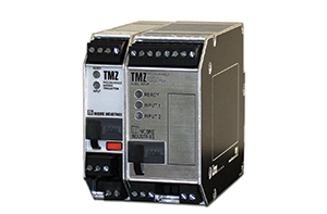
A: Yes it can be. The EMM can be used as a MODBUS RTU Master and query multiple TMZ Modbus RTU Slaves.
If the RTDs are in clusters of four or more you can use an EMM with one or more TIM modules instead of four or more TMZs for a more economical solution. A separate stand-alone EMM MODBUS Master can still be used to poll EMM and TMZ MODBUS Slaves.
The RS485 port of the EMM is used for either MODBUS RTU Master or MODBUS RTU Slave functions. The Ethernet port is used for MODBUS/TCP (Slave only) communications.
Do you want more information? Download the data sheet. Or visit the catalog.
Need to get price or availability or have a technical question?
Send us a message using E-Help.
Moore Industries has released an update to the THZ3 and TDZ3 Dual Input Smart HART Transmitter Datasheet. The THZ3 DIN unit now has Non-Incendive/Div 2 approval for use in the United States and Canada. This allows the THZ3 DIN unit to be installed in hazardous field locations closer to the process.
The THZ3 and TDZ3 offers all of the benefits of the previous TDZ2 and THZ2 Smart HART Transmitters but with several advanced features such as a Dual Input for Backup and Failover Protection, Average and Differential measurement and Low or High Select and Device Intelligence for smarter monitoring and control.
Remember that our Download Center remains your best place to find the most recent versions of product data sheets, installation manuals, PC configuration software and Device Description (DD) files, approvals and certificates, CAD drawings and more. Make sure you check that you have the latest version of the information you need.
Do you want more information? Download the data sheet. Or visit the catalog.
Need to get price or availability or have a technical question?
Send us a message using E-Help.
The WORM Flexible Temperature Sensor truly is flexible in a number of ways. Not only does it bend to accommodate awkward mounting positions and locations but it also comes with a myriad of mounting options. The new RTI-4 datasheet highlights some of the most common applications for the WORM:
Standard WORM Sensor; Lead Length with Overall Jacket* and Cord Grip
Model Number Example: SEN / CL1.5 / D25 / S316 / -WSPT14 -LL120 –GRIP [SEN]
Uses: Surface measurements where lead wire protection is not needed. Non-abrasive environment.
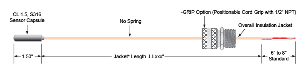
*Jacket Material is Teflon or Braided Fiberglass.
Standard WORM Sensor; Lead Length with Overall Jacket and Spring and Cord Grip
Model Number Example: SEN / CL1.5 / D25 / S316 / -WSPT14 –LL120 –SPR24 –GRIP [SEN]
Uses: Anytime you want the compressed spring to keep the sensor in contact with the well or hot surface. When used with the WORM Nose the spring adds weight to keep the sensor in the Nose. Increased protection of the lead wire against abrasion.
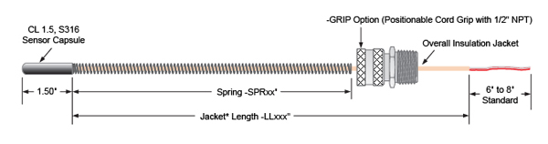
Standard WORM Sensor; Lead Length with Overall Jacket and SS Braid and Cord Grip
Model Number Example: SEN / CL2 / D25 / S316 / -WSPT14 –SSB120 –BOOT –GRIP [SEN]
Uses: The SS Braid provides excellent abrasion protection while maintaining flexibility of the lead wire. The braid and wire can easily round bends and should be used any time you need to pull the lead wire in adverse conditions.
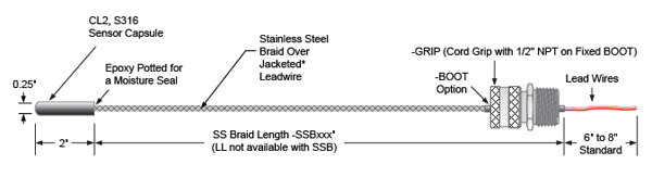
Standard WORM Sensor; Lead Length with Overall Jacket and Flex Armor and Cord Grip
Model Number Example: SEN / CL2 / D25 / S316 / -WSPT14 –FLEX84 –BOOT –GRIP –LL36 [SEN]
Uses: The Flex Armor provides mechanical protection for the lead wire. Used most often with surface mount fittings or when conduit or Panduit are not available for the lead wire. Protects against anything striking the lead wire.
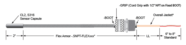
Direct Immersion of WORM Sensor with Flex Armor Cable and Cord Grip
Model Number Example: SEN / WSPT14 / D25 / S316 / -CL2 –FLEX24 –SSF11 –BOOT –GRIP [SEN]
Uses: This compression fluid seal fitting allows you to set the depth of the sensor and then lock it in. The same Flex Armor as above is used to protect the wires.
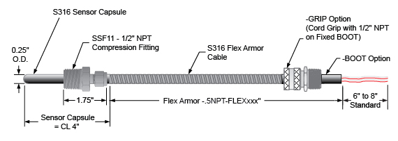
Do you want more information? Download the data sheet. Or visit the catalog.
Need to get price or availability or have a technical question?
Send us a message using E-Help.

ARC Advisory Group posted highlights of its recent ARC Industry Forum to their website. Several sessions focused on the “ongoing automation challenges facing end users across a variety of industrial sectors.” Many of the challenges faced by plant operators involved managing increasingly complex systems – especially when dealing with multiple generations of automation implemented in different stages of a plant’s expansion or refurbishing.
The result is an increasingly varied number of automation technologies deployed in plant settings. While automation professionals recognize the value of automation processes, many people outside of an infrastructure’s automation community do not understand the value of automation or take it for granted. According to ARC Advisory Group, the automation community needs to understand how to communicate the benefits of automation to senior decision makers and other stakeholders.
Moore Industries’ products help companies solve challenges in integrating diverse automation solutions – including plant expansions where installing additional wiring is cost-prohibitive or not possible. A prime example is the NCS NET Concentrator System, which provides a real-time signal gateway between the field or factory floor and your control strategy and is the ideal solution when you need to network new and existing “legacy” process sensors, instruments and final control elements with computer-based monitoring and control systems.
Other Recent Industry News:
Automation World has a piece on the rise of the Field Device Tool (FDT) standard to help establish “a common communication method between field devices and control or monitoring systems that are used to configure, operate, maintain and diagnose intelligent field instrumentation in both factory and process automation applications.” Moore Industries’ THZ3 and TDZ3 Dual Input Smart HART Temperature Transmitters are HART & DTM Programmable with user-oriented basic configuration for fast and accurate setup. They can be programmed or monitored with any FDT compliant host or program, such as PACTware, utilizing our DTM.
Control Engineering explored how using wireless transmitters to take measurements such as flow, pressure, temperature and level in hazardous areas can reduce the time, expense and difficulty associated with installing and maintaining traditional two-wire or fieldbus transmitters.
