

Search Problem Solvers
 Q. What is the least expensive way to speed up the response time of a sensor installed inside of a thermowell? We have a reactor associated with a quickly changing process and need to be able to control any sudden changes. What do you suggest?
A. We can suggest several solutions:
If you reduce the mass of the thermowell stem, which is the portion inserted into the process, sensitivity to the response will increase.
Another option is to add temperature sensitive paste to the inside of the thermowell to fill in the air space and allow temperature changes to more quickly conduct to the sensor sheath.
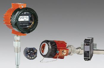
Our last recommendation is to reduce the sheath length, which you can do by using one of Moore Industries’ WORM flexible temperature sensors. The WORM has a very short sheath length of 1.5-inches and responds to temperature changes 13% faster than a longer fixed sheath. (Keep in mind: The longer the sheath length the longer the response time). Also, reducing the sheath diameter will speed up response. The WORM sensor also has a reduced tip outside diameter (OD) of 6mm. The shorter and smaller the OD of the sheath, the faster the response rate. Replacing your existing sensor with the WORM sensor should immediately show improved response time.
To read more about the WORM, download the data sheet.
You can also download the Getting Rid of Rigid White Paper for insights to using flexible sensors.
Do you want more information? Download the data sheet. Or visit the catalog.
Need to get price or availability or have a technical question?
Send us a message using E-Help.
 Q: We have several outdoor temperature applications where we measure the temperatures of pipes running alongside cooling towers. These sensors are in several different locations and zip-tied to the outer surface of the cooling pipes. Our problem has been that exposure to rain, sun and heavy snow causes signals to drop off or spike. We believe moisture is getting into the wire jacket and the environmental exposure is causing false readings. The sensors we use have a PVC jacket over the lead wires and it shows cracking over time. We need to replace the sensors and would like a 4-20mA output signal to go from our junction box out to the field instead of running the sensor lead wires all the way back to our monitoring system. What type of solution do you have for this?
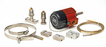
A: Surface mounted temperature measurements is an area Moore Industries excels in and we build a variety of mountable measurement devices. Our WORM sensors offer Flex Armor Cable or Stainless Steel braid options to provide greater protection from exposure. Also, we offer sensors that have Teflon insulated leads with a Teflon jacket that can withstand liquids and provide protection from cracking with a temperature tolerance from -200 to +500°F.
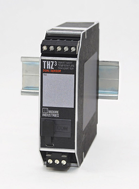
To secure the WORM sensor to your pipe, use our “CLAMP” fitting which uses a pipe band for a secure fit. We can add Flex Armor over the Teflon jacket and run it along the surface of the pipe and back to your junction box. At the junction box you can install one of our TRY/TRX or THZ3 two-wire loop powered Hockey Puck (HP) housed temperature transmitters to achieve a 4-20mA output that can be wired back to your monitoring system over your existing lead wires (we also have additional installation options if an HP transmitter will not fit in your existing junction box).
Do you want more information? Download the data sheet. Or visit the catalog.
Need to get price or availability or have a technical question?
Send us a message using E-Help.
 Q: Currently we monitor the temperature level in our oven with a thermocouple and let our PLC control the oven. We now need to implement a high-temperature Safety Instrumented Function (SIF). Do we need duplicate temperature sensors and do you have a Functional Safety device that can provide oven shutdown capability on high temperature?
A: A requirement of the SIF is for a safety function to be independent from the control system with the expectation that the safety loop will not fail should the regular process control loop incur a sensor, controller or any other failure. Therefore, it is recommended you not use the same sensing devices (thermocouple in your instance) for the safety function and control system. Other considerations to factor in are maintenance and proof testing of the SIF. If either affects the control system, interruptions to normal operation during this time will be experienced. If a common sensor is used, then a risk analysis must be performed.(Please refer to IEC61508 standard section 7.4.2.3 and ISA84/IEC61511 Part 1 11.2.10 and Part 2 11.2 for more information.)
To maintain a safe, operable system, SIL (Safety Integrity Level) guidelines state that your SIF would have an independent temperature sensor housed in a different thermowell. For improved safety, use of different technologies for these sensors avoids common cause failures in the control and safety functions; either different types of thermocouples or an RTD if temperature limits allow. Best practice is to duplicate transmission of the safety sensor signals to the control system. Such an arrangement can lead to improved diagnostic coverage by allowing signal comparison between control and safety sensors.
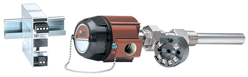
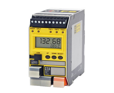
For this SIF, we recommended using products from Moore Industries’ Functional Safety Series which are independently assessed and certified by exida. The STA Functional Safety Trip Alarm can be used to monitor the oven’s thermocouple sensor and includes two user-configurable failsafe process trip alarms. It also has an isolated 4-20mA analog output signal which can be sent to the primary control system for comparison with the process control temperature signal.
If additional process relay outputs are required you can use the SRM Functional Safety Relay Module. The SRM accepts an input from one of the STA process relay outputs and offers three additional relays that can be used to drive other output loads.
The STA Functional Safety Trip Alarm and SRM Functional Safety Relay Module are available with IEC 61508 certificates from exida, safety manuals and FMEDA reports for your SIF calculations.
For more questions regarding application concerns and compatibility, contact us at
E-HELP EXPRESS.
Do you want more information? Download the data sheet. Or visit the catalog.
Need to get price or availability or have a technical question?
Send us a message using E-Help.
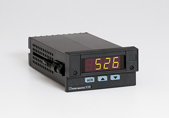 Q: My Model 330R process monitor with display has configurable threshold output relays that I need to set in order to activate a 125Vdc battery powered circuit which is part of a failsafe control room application. How would I set these up when standard instrument relays are rated at 125/240Vac and 24Vac/dc?
A: The Model 330R process monitor threshold alarm relays are ‘compact’ relays designed to activate ‘external intermediate’ relays. High DC voltage (and/or current) switching is always performed on the output contacts of a stand-alone external intermediate relay because high voltage DC switching (opening of relay contacts) creates a sustained high temperature plasma arc. This arc cannot be readily extinguished in a small instrument package, therefore, the relay sacrificially absorbs the excess energy. This ultimately requires replacement of the relay however this is a more economical alternative to replacing a blown panel meter.
A proven solution for the high DC current at high voltages need is to use Form ‘X’ style relays with a built-in magnet (this is a readily available industrial relay product which also comes in a DPDT configuration) as your intermediate relays. The coils of these intermediate relays are driven by the standard voltage/current relays as in the Model 330R series. A quick Internet search of ‘Form X relay schematic’ will provide you with wiring instructions.
A Form X relay has an optional magnet (recommended for DC voltage applications). As the relay opens, a small to moderate sized electrical plasma arc always occurs. The magnet pushes the arc away from a straight line and onto a longer distance pathway. Thus the Form X relay’s mechanical doubling of contact separation distance along with the properties of the installed magnet significantly increase the arc travel distance and more quickly extinguish the DC plasma arc. When wiring for DC switching, be mindful of the polarity of the electrical contact pathway through the magnetic field to ensure that you are extending the arc distance.
To optimally select a Form X relay:
- Perform an Internet search for ‘Form X relay with magnetic blowout’
- Specify a clear relay package referred to as an ‘ice cube’. This permits visual inspection of the relay’s internal movements.
- Specify the relay ice cube package with either a DIN rail socket or a panel mount socket with a retaining clip so the relay does not fall out of the socket as may occur in high vibration applications.
To learn more about the Model 330R, download the datasheet.
Do you want more information? Download the data sheet. Or visit the catalog.
Need to get price or availability or have a technical question?
Send us a message using E-Help.
Q. We have several short thermowells in our process, ranging from 2-inches to 6-inches. Our process is very stable, but we have noticed a temperature measurement shift when the outside air temperature rises or falls. We have tried calibration, but it still doesn’t correct the temperature swing we see. What would you suggest we change that will prevent these temperature swings?
A. The most active area of a sensor can be approximated as 4 to 10 times the length of the installed element. As temperatures change outside the process, the upper portion of the sheath is exposed to these fluctuations. This part of the sheath senses a temperature difference then measures it, influencing the temperature along the full length of the sheath. We regularly see this occurrence when calibrating sensors with long sheath length exposed outside of calibration baths. The only way to measure true process temperature is to keep the sheath as short as possible.
Moore Industries manufactures the WORM, a sensor with a very short sheath length of 1.5-inches. Worm sensors are spring loaded to stay at the bottom of the thermowell. They have a faster response time and the lead wires do not measure temperature changes outside the process connection. They do not sense any outside temperature swings and only measure temperature inside the bottom area of the thermowell.
To read more about the WORM, download the data sheet.
You can also download the Get Rid of Rigid White Paper for more information on using the WORM in your process.
Do you want more information? Download the data sheet. Or visit the catalog.
Need to get price or availability or have a technical question?
Send us a message using E-Help.
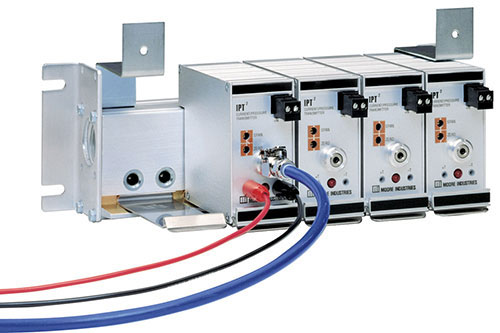 Q: We need to combine a new system for reading tank levels with an existing system by replacing a Hagan instrument with a new Rosemount device. However, we need to ensure we can still run an existing 3-27psi pneumatic chart recorder. We’re considering using an I/P, but aren’t sure if the 4-20mA output from the new transmitter can be piggybacked. Is this possible?
A: If the 4-20mA loop can drive the load presented by Moore Industries’ I/P then you can piggyback the output and run your chart recorder. Our model IPT2 (DIN rail mounted) consumes 7.5V of the available loop compliance voltage. Our model IPX2 (field mounted) consumes 5V of the available loop compliance voltage. Both models offer a 3-27psi output.
For additional information, download the datasheet: IPT2 and IPX2.
Do you want more information? Download the data sheet. Or visit the catalog.
Need to get price or availability or have a technical question?
Send us a message using E-Help.
 Q: You have a product called HART Interface Module (HIM) that will pull the 2nd, 3rd and 4th HART variables from a transmitter signal and create one 4-20mA signal for each. Do you have or know of an instrument that will take multiple 4-20mA signals and output them on one 4-20mA signal as HART dynamic variables? I would like to read three transmitters on one 4-20mA signal by reading the variables on my DCS system.
A: We have two products that take multiple inputs and output a HART signal that can be read by a HART host. Those two products are the TCM and the THZ3/TDZ3.
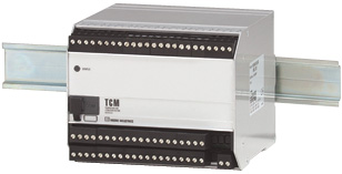
The TCM is a 16 channel input module that accepts multiple temperature, resistance and millivolt signals and offers a HART output or a MODBUS RTU output. For 4-20mA inputs the TCM accepts them across a resistor or shunt input as a mV input. Those signals can then be read by a HART host using a custom HART command. For a MODBUS RTU output a separate HART to MODBUS converter, called the HMC, is used. For more information on the TCM and HMC (which together comprise the TCS) download the TCS data sheet.
The THZ3/TDZ3 Smart HART Temperature Transmitter can accept two (not three) 4-20mA
signals and write them to two of the HART dynamic variables riding on the analog 4-20mA
output.
A wiring diagram showing how to wire the THZ3 to accept two 4-20mA input signals is available in the Installation Manual which you can download here. For more information, download the THZ3 data sheet.
For more information on the HIM, download the data sheet.
Q. We have been using 3-wire RTDs in our process for years and are required to check the calibration once every 6 months. Each time we have checked the sensors we’ve noticed they have drifted. This requires us to re-calibrate our temperature transmitters. Do you have something you can suggest to help us reduce the drifting problem we regularly see in these sensors?
A. The problem with 3-wire RTDs is that the lead wires build up small amounts of corrosion causing a lead wire imbalance which results in measurement errors. If these are Platinum 100 ohm RTDs, just one ohm of resistance change on any lead wire can represent a +4.7°F degree error. We suggest using 4-wire RTDs which compensate for unequal resistance in the lead wires. For this to be an option your temperature transmitters need to accept a true 4-wire sensor input. Some temperature transmitters, PLCs, and DCS input cards only accept 3-wire RTDs. Others indicate a place to connect a fourth wire, but do not use it for measurement.
You can also use Class A RTDs with 4 wires and a transmitter that can accept and be calibrated with a 4-wire RTD. Our Class A element RTDs with a .06% accuracy have been cycled for 1000 hours, and will hold their accuracy for a 5 year period.
You can learn more about using 3-wire and 4-wire RTDs in the white paper: A Practical Guide to Improving Temperature Measurement Accuracy.
These Moore Industries temperature transmitters are designed to accept true 4-wire RTDs: RIY, STZ, TCS, TDY, TFZ, THZ, THZ3/TDZ3, TPZ, TRY, TRX. For these and other Moore Industries temperature solutions, visit our Temperature Sensors, Transmitters and Assemblies page.
Do you want more information? Download the data sheet. Or visit the catalog.
Need to get price or availability or have a technical question?
Send us a message using E-Help.
 Q: I would like to use either FDY/PRG/4-20MA/12-42DC [HPDN] or FDY/PRG/4-20MA/12-42DC [BH2NG] and I want to install it in a control panel enclosure rated Type 4X. I need to ensure it is suitable for Class I, Div 2. Which one is the best solution?
A: The FDY/PRG/4-20MA/12-42DC [HPDN] without the BH2NG enclosure is Class I, Div 2 rated. It meets the Div 2 requirements when installed in your Type 4 box. You can download the certificate here.
The FDY/PRG/4-20MA/12-42DC [BH2NG], is an explosion proof transmitter approved for use in Class I, Div 1 hazardous areas. This is the same FDY device except it is housed inside the explosion proof/flameproof BH2NG enclosure. This BH2HG enclosure is also rated Type 4X & IP66 which means that it offers sufficient environmental protection to allow it to also be classified as a Class I, Div 2 or Non-Incendive device. The FDY/PRG/4-20MA/12-30DC/-ISF with the [HPDN] housing designation or enclosed in a BH type housing carries intrinsically-safe approvals.
Download the FDY datasheet.
Do you want more information? Download the data sheet. Or visit the catalog.
Need to get price or availability or have a technical question?
Send us a message using E-Help.
Q. I have a temperature application that requires a 12-inch thermowell which can withstand a high temperature of 2,000°F. Most of what we have been using becomes brittle and breaks off at the tip. What would you suggest we use, and what type of sensors do you have that will work for us?
A. We have several different types of metals we can suggest with maximum temperatures up to 2,160°F. Materials that will work well for the thermowell in your application are SS446, SS310, and Inconel 600.
For the sensor type, we recommend a thermocouple Type “K” with Inconel 600 material for the sheath. Also, using 2-inches of thermal-lagging for the thermowell will reduce heat going into the head.
If possible, remote mount the temperature transmitter away from the process connection. Even though Moore Industries temperature transmitters are rated up to 185°F, it could get too hot inside the head if it were mounted directly on top of the process. If you must mount the transmitter near the process connection, we suggest using a stainless steel housing and a ceramic terminal block to terminate the sensor at the process.
Do you want more information? Download the data sheet. Or visit the catalog.
Need to get price or availability or have a technical question?
Send us a message using E-Help.
 Q: We have an R-BOX in a Class 1 Div 2 location with a 120VAC instrument inside. Is this enclosure rated for this atmosphere? It does not appear to have a very good seal for this environment.
A: The R-BOX was designed to meet a Type 4X and IP66 rating, which is suitable for housing a Div 2 approved device. The hazardous area protection is provided by the non-incendive nature of the Div 2 rated device mounted inside. The enclosure simply needs to provide protection from the ambient elements or other flying conductive material.
Learn more by downloading the R-BOX datasheet.
Do you want more information? Download the data sheet. Or visit the catalog.
Need to get price or availability or have a technical question?
Send us a message using E-Help.
 Q. We want to measure bearing temperature in our motors to alert us of overheating. We have used a type of sensor which inserts into the side of the motor, but they leak and fail often. We would like to put something on the surface of the motor outside of the bearing housing, but we do not want something welded to the housing. What can you suggest?
A. The best solution for your application is a WORM sensor with a Magnetic Pad (-MPAD). The -MPAD has 40lbs of attraction and will hold up to a vibrating surface. We also suggest adding our 30G option to the RTD, in order to protect the RTD element inside the sheath from high vibration during motor operation. Standard fixed length sensors cannot withstand this vibration over time. The -MPAD with WORM sensor is easy to install on any ferrous metal surface.
Download the RTI-3 datasheet for more information.
Do you want more information? Download the data sheet. Or visit the catalog.
Need to get price or availability or have a technical question?
Send us a message using E-Help.
 Q: I am evaluating the SIX 2-wire Signal Isolator and Converter. Is this device auto-calibrated or will we need to calibrate it ourselves? Does it require two separate power supplies? The specs state that the output is loop powered but I am not clear on the input. Also, is it a problem if we supply both the input and output with the same power source? In our case, it would be the 53.5VDC power supply in the loop currently. We would need to run a parallel path. The input is intended to be a 4-20mA.
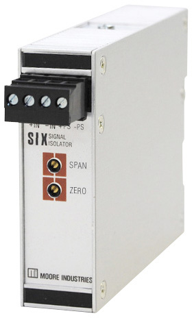
A: The SIX is provided pre-calibrated from the factory for the input and output indicated in the model number. The device has potentiometers accessible on the front panel for making adjustments to the zero and span.
The SIX derives its operating power from the voltage that is applied to its output. It consumes 12V of the available voltage applied to its output. The SIX accepts a voltage or current input. If the input is 4-20mA, then the SIX will add 50 ohms of impedance to that loop.
Regarding supplying both the input and output with the same power source, the primary purpose of the SIX is to provide input to output galvanic isolation. Using the same power supply for both would defeat that isolation.
Do you want more information? Download the data sheet. Or visit the catalog.
Need to get price or availability or have a technical question?
Send us a message using E-Help.
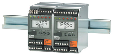
Q: We have been using your SPA series temperature transmitters in our hydroelectric power plants with excellent results. These devices have high protection against electromagnetic interference. We would like to purchase temperature transmitters for head mounting and rail mounting that have the same high level of isolation and protection against electromagnetic interference. The sensors are 10 Ohm Cu three wire RTDs and they represent the temperature of generator windings in the hydroelectric power plant.
A: Model SPA/TPRG/2PRG/U/-AO [DIN] provides 0.25 mA RTD excitation current. If it is performing well then our PC configurable temperature transmitters, which have the same excitation current, should also perform well. In that case we recommend the TRY series. The head mount style is model TRY/PRG/4-20MA/10-42DC [LH2NS]
If your SPA has the SP2 option instead (Model SPA/TPRG/2PRG/U/-AO-SP2 [DIN] ), that option provides 5mA of excitation current to the 10 ohm RTD instead of the usual 0.25mA. This ensures that a robust input signal from the RTD to the SPA resists interference from the generator’s very strong electro-magnetic fields.
The choices available for a head mounted transmitter with similarly high current RTD excitation are limited. Bear in mind that the objective when designing RTD temperature transmitters is to reduce the excitation current as much as possible to minimize self-heating of the RTD, thereby maximizing the measurement accuracy.
Also due to the reduced power budget of loop powered transmitters there isn’t sufficient power available for the 5mA excitation current of the SP2 option.
A possible solution is one of our older analog loop powered transmitters, the RBX series, which has a relatively high excitation current of 1mA. The RBX, however, is a strictly analog design and must be specified according to the intended resistance range instead of temperature span. For example, for 10 ohm Cu and 0-200 deg C, the resistance is 9.035 to 16.776 ohms. The span is 7.741 ohms. The 7.741 span falls within the 3W5-10 input range.
The head mounted model number is: RBX/3W5-10/4-20MA/12-42DC/-EZ9 [BH2NS].
Do you want more information? Download the data sheet. Or visit the catalog.
Need to get price or availability or have a technical question?
Send us a message using E-Help.
Q: I need confirmation that the THZ2 is a functional like-for-like replacement for the THZ and that basically it will perform the same.
A: With the exception of the THZ/PRG/4-20MA/12-42DC [DH2NG], which has an integral display, the THZ2 has all of the functions of the THZ and the same form and fit.
However, we suggest you consider the newer THZ3, since the THZ2 is being phased out (although it will continue to be available while supplies last). The THZ3 has all of the functions of the THZ2 and the same form and fit. The THZ3 offers additional functionality over the THZ2, can accept two sensor inputs, and utilizes PACTware for PC configuration in addition to HART programmability.
Other features found in the THZ3 that are not included in the THZ are:
- Backup and Fail-Over Protection allows either of the sensors or inputs to be designated as the primary measurement, with the secondary input acting as the backup sensor in case of primary sensor failure.
- Average and Differential Measurement allows you to average the two input measurements or select the differential (A-B or B-A) or absolute differential between the two inputs.
- High-Select and Low-Select Feature enables the transmitter to continuously monitor two separate inputs and designate either the highest or lowest input to represent the analog output.
- Dynamic Variable Mapping permits the user to assign either input or the calculated result of inputs to any of the four HART variables (PV, SV, TV or QV) that can be read by any HART compatible host system.
- Smart Range Alarms offer four HART alarms set to any input or calculated input that detect when the variable is within or outside user preset limits.
- High Availability Option enables the user to select how the AO behaves when there is an input failure or out-of-range value detected by the transmitter. This prevents nuisance alarms on startups or batch process shutdowns.
Download the THZ3 data sheet.
Do you want more information? Download the data sheet. Or visit the catalog.
Need to get price or availability or have a technical question?
Send us a message using E-Help.
 Q: You have a product called HART Interface Module that will pull the 2nd, 3rd and 4th HART variables from a smart HART transmitter and create one 4-20mA signal for each. Do you have or know of an instrument that will take three 4-20mA signals into it and place themdin on one 4-20mA signal as the 2nd, 3rd and 4th variable? I would like to read three transmitters on one 4-20mA signal by reading the variables on my DCS System.
A: We have three products that can take multiple analog inputs and provide that signal data in the form of HART protocol. Those products are the TCM and THZ3 / TDZ3, which are temperature input devices that can take a 4-20mA input across a resistor (shunt) as a mV input.
The TCM is a 16-channel temperature input module that can be polled by a HART master using a device-specific HART command. This HART command retrieves all 16 channels of PV data in one HART message packet.
The THZ3 Dual Input Smart HART DIN-Rail or Field Mount Temperature transmitter can accept two (but not three) 4-20mA signals and write them to two of the HART dynamic variables riding on the analog 4-20mA output signal.
The TDZ3 has the same functionality as the THZ3 but includes a display and can be field mounted in hazardous or non-hazardous areas or mounted on DIN-Rail.
Do you want more information? Download the data sheet. Or visit the catalog.
Need to get price or availability or have a technical question?
Send us a message using E-Help.
 Q: I am looking to take a signal from an analyzer and send the analog output signal to four different locations. Do you have a product that can help me with this?
A: We offer a 4-channel output loop powered isolator and a line powered single input to dual output isolator.
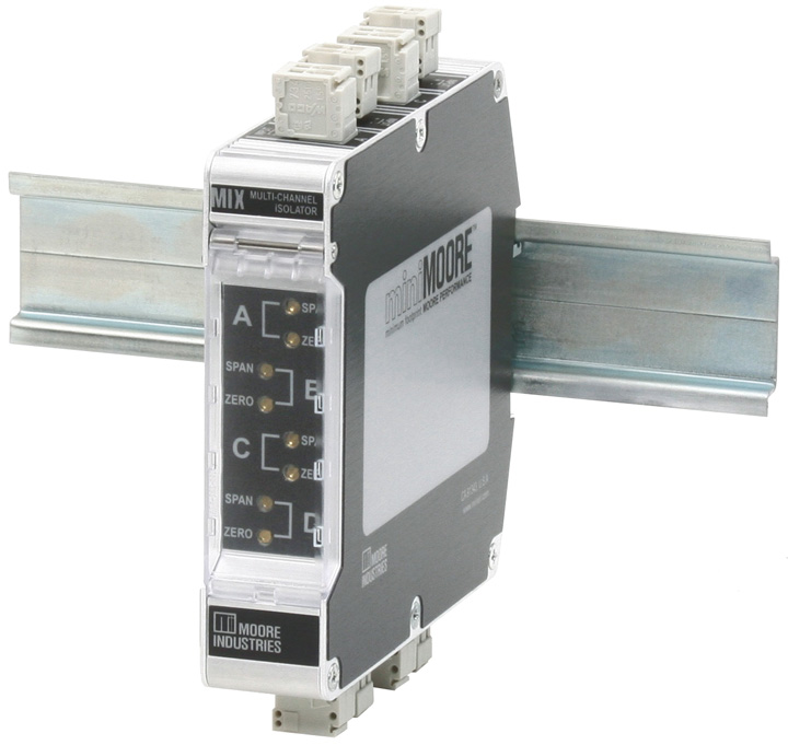
If the receivers at the four locations can supply loop voltage to their respective 4-20mA inputs, then the 4-channel output loop powered MIX isolator (Model: MIX/4X4-20MA/4X4-20MA/12-42DC [DIN]) will work. Wire your 4-20mA signal in series to the four inputs of the MIX.
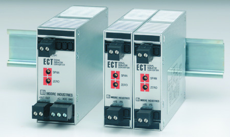
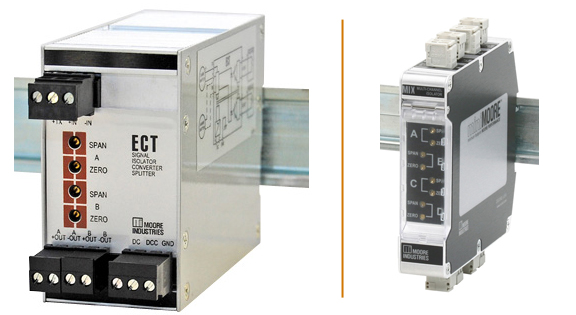
If the receivers at the four locations have passive (sinking) 4-20mA inputs, then you can either use two of the line powered ECT splitters or two of the dual channel MIT isolators (Models: ECT/4-20MA/2X420MA/117AC/-TX [DIN] or MIT / 2XPRG / 2X4-20mA / U [DIN]). Wire your 4-20mA signal in series to the inputs of the two ECT/MITs.
Do you want more information? Download the data sheet. Or visit the catalog.
Need to get price or availability or have a technical question?
Send us a message using E-Help.
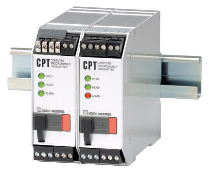
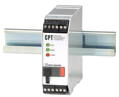 Q: I want to replace a THZ Temperature Transmitter (Model THZ/PRG/4-20MA/12-42DC [DIN]) with a CPT PC-Programmable Temperature Transmitter (Model CPT/TPRG/0-20MA/117AC/-C-RF [DIN]). The THZ unit we are replacing gets its power from the 4-20mA current loop while the CPT unit is going to be powered by 120Vac. Does the CPT need to be specified as "source" or "sink" to work as a drop-in replacement for the THZ unit?
A: The default version of the CPT provides voltage on its output (source). If you would like the output to be passive so it can be wired to an active (voltage supplied) input, specify the "-SINK" option. The CPT will still require 120Vac power on the power terminals.
Note that the newer two-wire output loop powered THZ3 Dual Input Smart HART Temperature Transmitter (Model THZ3/PRG/4-20MA/12-42DC [DIN]) is now available.
Q: My concern is that we will damage the unit or the equipment it is connected to it if we specify the wrong type of output. This unit will be connected to an Allen Bradley 4-20mA analog input module. The previous THZ device got its power from the analog input module so I believe the correct specification would be "sink" for the CPT. Is this correct? Also, can the "source" or "sink" option be changed in the field or does this have to be set at the factory?
A: You are correct that you will need to choose the "-SINK" option on the CPT. The choice of "source" or "sink" for the CPT must be specified in the model number and supplied from the factory that way. It cannot be field changed. Your complete model number for this application would be: CPT/TPRG/0-20MA/117AC/-C-RF-SINK [DIN]. Note that you have also selected an auxiliary alarm contact and enhanced RFI/EMI protection.
Do you want more information? Download the data sheet. Or visit the catalog.
Need to get price or availability or have a technical question?
Send us a message using E-Help.
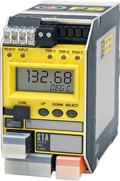 Q: I need to use the STA Safety Trip Alarm in a hardwired panel. Is it possible to configure two different levels of alarm for each of two relays in the STA, in order to have two different trips (one for each relay)?
A: Only one set point can be assigned to each alarm relay of the STA. However the dead-band is adjustable from 0% to 100% of the input span. Therefore you can specify one signal level at which the relay engages and another for when it disengages. If your input signal is 4-20mA, you can connect it in series to the inputs of two STAs in order to obtain 4 independent relay/setpoints.
Q: To clarify my situation: if I have a 0 to 100 bar transmitter, can I trigger Relay 1 at 25 bar and Relay 2 at 75 bar? We need to do this in order to shut down two different pieces of equipment at these pressure levels.
A: This is a typical function of the STA. One relay setpoint is often used for a warning at one level while the second relay setpoint is used for shutdown at the next level.
Do you want more information? Download the data sheet. Or visit the catalog.
Need to get price or availability or have a technical question?
Send us a message using E-Help.
 Q: We are in need of a signal converter that converts a 4-20mA logarithmic signal into a 4-20mA linear signal. We need one input and one output per device. Do any of your devices perform this function?
A: We offer several models of signal converters which have look-up table linearization/characterization capability.
The SIY is an output loop-powered unit that can be configured for up to 85 ordered pairs. With this model, each ordered pair must be keyed in using the provided configuration software.
The CPT is a line-powered model that can be configured for up to 128 ordered pairs. The ordered pairs are computed with a spreadsheet, saved as a two column CSV file and then loaded into the provided configuration software. The configuration is then loaded into the CPT.
 With both models you specify the X and Y values so you can cluster points at the most non-linear part of your table.
Do you want more information? Download the data sheet. Or visit the catalog.
Need to get price or availability or have a technical question?
Send us a message using E-Help.
 Q: We are a boiler/burner company dealing with a rising amount of computer-based burner controls. We have installed several and have some blowers that are controlled by VFDs (Variable Frequency Drives). We have run into issues with noise on certain systems. We get occasional problems with 4-20mA feedback from the VFD despite going through the proper grounding techniques. We are wondering if installing an opto isolator on the feedback loop might eliminate our issue. We have used the SIX Signal Isolator many times on the signal going to the VFD to offset impedance issues on the VFD. Can we put an opto isolator on both signals?
A: Whether the SIX or another isolator will cure your problem depends on the nature of the noise and how the loop is energized. Sometimes you can install an isolator without additional analysis and see if it works.
If you have data about the noise, compare it to the noise rejection specification of the isolator. For example, the Common Mode Rejection for the ECT-DIN Signal Isolator exceeds 95dB @ 60Hz with a limit of 1500 Vrms.
When selecting the appropriate isolator, take into account which device is providing the loop voltage on the input and output sides. Per the ECT datasheet, you can see that it is available as an output loop powered, input loop powered or line powered device.
Do you want more information? Download the data sheet. Or visit the catalog.
Need to get price or availability or have a technical question?
Send us a message using E-Help.
 Q: I am looking for a device to create a temperature switch. I currently use a simple temperature switch with a 230°F setting, but at times the temperature of the unit goes over 400°F briefly and destroys the switch. I need to be able to hook a thermocouple up to the device and program a setpoint (with no display required) and have a set of dry contacts open when the temperature rises above the setpoint.
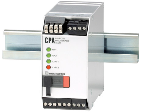
A: Our model CPA PC-Programmable Alarm can accept a thermocouple or RTD input and trip a relay based on the setpoint that you have configured. It can be configured using our software and a USB cable.
Do you want more information? Download the data sheet. Or visit the catalog.
Need to get price or availability or have a technical question?
Send us a message using E-Help.
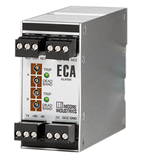
Q. We would like to use the ECA-DIN in a seismic application. In a worst case scenario of an earthquake, the ECA-DIN must retain its position. We are concerned about the robustness of DIN rail mounting. Is the ECA available with a bolt down option?
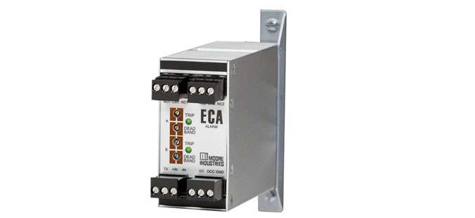
A. We can supply the ECA with side flanges for more robust gearplate mounting instead of the usual DIN rail mounting.
Do you want more information? Download the data sheet. Or visit the catalog.
Need to get price or availability or have a technical question?
Send us a message using E-Help.
Q: We have an existing Rosemount 1151DP tied to a Provox DCS. We also have a Moore Industries DDA 4-Wire Current and Voltage Alarm in the system to provide a Flow Switch Low and Flow Switch High interlock to our gas supply valves. Will newer products from Moore Industries provide more – or better – protection than the DDA?
A: The STA Safety Trip Alarm and SPA2 Site Programmable Alarm have alarm functions and can be used instead of the DDA. Both products have FMEDA reports which define the Probability of Failure on Demand and can provide a better degree of protection than the DDA. Additionally, the HIM HART Interface Module has alarming functionality that could also be used with the 1151DP transmitter.
The STA monitors the analog signal and is specifically designed for IEC 61508 applications. It is approved by exida for use in Safety Instrumented Systems (SIS) up to SIL 2 and in redundant architectures (1oo2, 2oo3, etc.) up to SIL 3.
Like the STA, the SPA2 can also monitor the analog signal and provides up to four alarms, a display, and an optional 4-20mA retransmission. The SPA2 is our most popular alarm choice for loops that are not specifically designed in accordance with IEC 61508/61511The HIM monitors the digital component of a HART signal and can be specified with up to two optional relay outputs, which can be configured for signal level alarms or for a number of HART status bits. It can be used to provide diagnostic coverage for a HART transmitter since it monitors the transmitter’s status bits.
Do you want more information? Look up a data sheet to download. Or visit the catalog.
Need to get price or availability or have a technical question?
Send us a message using E-Help.
Q: I need a 4-wire isolator and want to see if your MIT Multi-Channel Signal Isolator will work in my application. I have several 4-wire transmitters where I need to split and isolate the output signal to receivers that are passive (not powered). Will the MIT work provided that I supply 24Vdc power to the unit?
A: The MIT appears to be a perfect fit for your application. MIT’s input is passive, so it is compatible with the active output of a 4-wire transmitter. Because its outputs are active, they are compatible with the passive inputs of the receiver devices. In addition, it uses a universal power input, so it will accept 24Vdc power.
Do you want more information? Download the data sheet. Or visit the catalog.
Need to get price or availability or have a technical question?
Send us a message using E-Help.
Q: I am looking for a differential temperature transmitter. We have used the SPT in the past and know that it will work, but I don’t know if you can use two inputs of two different 4-wire RTDs with the SPT.
A: The SPT has only four input terminals; therefore the number of RTD wires is limited. For differential temperature, one RTD can be a 3-wire and the other RTD can only be a 2-wire. The lead length compensation wire of the 3-wire connection compensates for the lead length of both RTDs. This is only useful if you make sure that all five wires have identical resistance.
To answer your question, you may use two 4-wire RTDs, but you cannot connect all of the wires unless you do it as described above. Wiring details are shown in Figure 17 of the installation manual.
A better option is to use our DIN rail mounted THZ3 HART temperature transmitter, a new model which can accept two three-wire RTDs and provide a differential measurement output. The configuration of the THZ3 is done by utilizing DTMs with PACTware on your PC or by using a HART compatible handheld device or HART host.
Details about the input connections of the THZ3 are in Figure 2.2 of the installation manual.
Model Example: THZ3/PRG/4-20MA/12-42DC [DIN]
Do you want more information? Download the data sheet. Or visit the catalog.
Need to get price or availability or have a technical question?
Send us a message using E-Help.
Q: I am interested in an ECA alarm unit, model #: ECA/4-20MA/DH1H1/24DC/DIN. I have three questions:
1. I have a need for three different trip setpoints based on the same transmitter input. How can I accomplish this with the ECAs? Can I use two ECAs using the second ECA with a 1-5VDC input or can the 4-20mA signal be run in series through both ECA inputs?
2. Do I need to specify the -RF option to get the RFI protection? And is the testing for both radiated and conducted susceptibility (RS103, CS114, CS115)? Is it possible to see the test report for the EMI/RFI testing?
3. Is DIN-rail the only mounting option?
A: To answer your three questions:
1. Your 4-20mA signal can be connected in series to the inputs of more than one ECA, each of which with a 50 ohm load on the loop. Alternatively, you can use a SPA2 Limit Alarm Trip (Model #: SPA2/HLPRG/4PRG/U [DIN]) which has four setpoint relay outputs.
2. The ECA-DIN has RFI/EMI Protection to 10V/m, 20-1000MHz for which the trip point would not be affected by more than 0.1% of span. It conforms to the following EMC specifications:
EN50081-2, 1993, Generic Emissions Standard, Industrial Environment.
EN50082-2, 1995, Generic Immunity Standard, Industrial Environment.
EN61010-1, 1995, Safety requirements for electrical equipment for measurement and control use.
3. Both the ECA-DIN and the SPA2 are designed for DIN rail mounting; however, we also offer them with options for flange mounting.
Do you want more information? Download the data sheet. Or visit the catalog.
Need to get price or availability or have a technical question?
Send us a message using E-Help.
Q: We have been using Moore Industries DCA series switches for some time. Is there a like-for-like digital microprocessor-based replacement available?
A: The SPA2 series is a microprocessor-based design with all of the capabilities of nearly any permutation of the DCA. It does have a different form and fit, so we will need to know the complete model number of your DCA unit in order to recommend a SPA2 model.
The most common type of DCA mounts to a back panel with four screws, such as model DCA/4-20MA/DH1L1/117AC [UB]. We can provide the SPA2 with the same mounting bracket so that it fits the same footprint and hole pattern.
Do you want more information? Download the data sheet. Or visit the catalog.
Need to get price or availability or have a technical question?
Send us a message using E-Help.
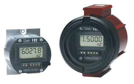
Q: I am monitoring up to 13600 Hz from a magnetic pickup on a gas turbine for speed indication and would like to use the FDY Frequency-to-DC Converter. Are either the PRG input or the 10-250V input handle this frequency?
A: Both input options can handle this frequency.
Normally the PRG input is correct for magnetic pickups. Some of them will put out a pulse voltage above the FDY's max of 30VAC, but it can be lowered by moving the pickup farther from the target. Use the FDY/10-250AC if you know for sure that the voltage pulse will be above the FDY/PRG’s upper limit. However, with this model, the pulse must be at least 10VAC.
Please note that the FDY with the 10-250AC input is not available with I.S. approval.
Do you want more information? Download the data sheet. Or visit the catalog.
Need to get price or availability or have a technical question?
Send us a message using E-Help.
Q: I have a question about the ECA-DIN Current and Voltage Alarm with the DH1L1 (Dual, High/Low, Failsafe) output option. The literature for the product says that "the failsafe relays are de-energized in an alarm condition or during power loss to the unit." Is this statement also true if there is a loss of input signal such as a broken wire?
A: The Failsafe setting means that the relay coils are de-energized in the alarm state. Naturally, if power is lost they will be de-energized. In case of loss of signal, the ECA will perceive the condition as a low signal and behave accordingly. That is, if you have a low alarm setting, the alarm will be activated. If you have a high alarm set, it will not be activated.
If you need more functionality such as being able to discern between a low signal and a lost signal, we recommend the SPA2. Unlike the ECA, it is a microprocessor-based design. This means that it can be configured for a variety of alarm and input signal conditions.
Do you want more information? Download the data sheet. Or visit the catalog.
Need to get price or availability or have a technical question?
Send us a message using E-Help.
Q: We are looking to take an RTD or thermocouple signal input and output it to two 4-20mA outputs. We also could take the same temperature input and output the same signal twice. What are our options?
A: Using our HIM HART Interface Monitor along with a HART temperature transmitter such as the THZ3 is the most accurate solution. The HIM polls the THZ3 via HART and offers up to three separate and isolated analog outputs. Other options include::
A loop-powered TRY temperature transmitter and the ECT-DIN signal splitter. The splitter provides the loop power to the temperature transmitter and receives its signal. It then provides two isolated outputs. The ECT-DIN can be powered with 24DC, 117AC or 230AC.
Models:
•TRY/PRG/4-20MA/10-42DC [DIN]
•ECT/4-20MA/2X4-20MA/117AC/-TX [DIN]
A temperature transmitter such as the CPT and a signal isolator such as the ECT-DIN that are both line-powered. The output of the transmitter is to be connected in series to the input of the isolator and to one of your two loads. The output of the isolator goes to your other load.
Models:
•CPT/TPRG/0-20MA/117AC [DIN]
•ECT/4-20MA/4-20MA/117AC [DIN]
Do you want more information? Download the data sheet. Or visit the catalog.
Need to get price or availability or have a technical question?
Send us a message using E-Help.
Q: I want to transmit temperature readings from 44 different four-wire RTDs over MODBUS using your TMZ PC-Programmable MODBUS Temperature and Signal Transmitter. Can I use the EMM Ethernet/MODBUS Interface Module of the NCS NET Concentrator System® to concentrate the outputs of the TMZ? I would like to have the EMM configured as a MODBUS RTU Master and the TMZs as MODBUS RTU Slaves and then output from the EMM as a MODBUS/TCP to my control system. Can this all be done?
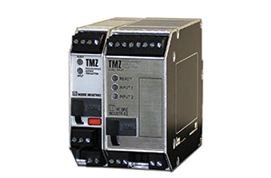
A: Yes it can be. The EMM can be used as a MODBUS RTU Master and query multiple TMZ Modbus RTU Slaves.
If the RTDs are in clusters of four or more you can use an EMM with one or more TIM modules instead of four or more TMZs for a more economical solution. A separate stand-alone EMM MODBUS Master can still be used to poll EMM and TMZ MODBUS Slaves.
The RS485 port of the EMM is used for either MODBUS RTU Master or MODBUS RTU Slave functions. The Ethernet port is used for MODBUS/TCP (Slave only) communications.
Do you want more information? Download the data sheet. Or visit the catalog.
Need to get price or availability or have a technical question?
Send us a message using E-Help.
Q: Do you have or do you know of a product that will filter out AC noise on an unshielded pair of wires carrying a 4-20mA signal over a distance of approximately 400 feet?
Top of Form
A: Any of our isolators have a common mode rejection AC filtering capability and can be used for this kind of application.
One popular and versatile option for this is our ECT line. You can see it for yourself by checking out the datasheet, which contains all three types (input loop powered, output loop powered, and line powered.)
Do you want more information? Download the data sheet. Or visit the catalog.
Need to get price or availability or have a technical question?
Send us a message using E-Help.
Q: Could you let me know the specific instances where the Fault Alarm trips on the STA Safety Trip Alarm are used?
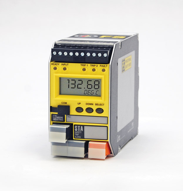
A: The Fault Alarm (Alarm #3) is permanently set as a latching fault alarm that will trip if internally diagnosed faults or external faults – such as the loss of sensor or a “bad quality input” – occur. This alarm will trip without affecting the other relays being used to monitor the process. It can be used to warn of a failure without tripping more critical process alarms or shutting down the process.
More information can be found on Page 58 of the STA/TPRG Installation Manual.
Do you want more information? Download the data sheet. Or visit the catalog.
Need to get price or availability or have a technical question?
Send us a message using E-Help.
A plant upgraded to new Smart HART® field transmitters but was still using their original field-mounted isolators. This meant that engineers in the control room were unable to access the HART transmitters – mitigating the benefits of performing the upgrade.
Moore Industries solved this problem with an installation of SSX HART Isolators. They offer full isolation and seamless HART communication capabilities with field transmitters including:
- Unlike traditional isolators, the SSX allows the HART signal to "pass" through so that critical HART diagnostic data can be read from the control room.
- HART PV data and status information is available at any termination point on both sides of the isolator..
- Calibration, field configuration or interrogation of the HART field transmitter can be accomplished from the host control system or asset manager..
The two-wire (loop powered) SSX and four-wire (line/mains powered) SST are part of the FS Functional Safety Series from Moore Industries and are exida-approved for use in an SIS up to SIL 3 in monitor mode, where only the input circuit is part of the safety function. For single use mode, the SSX and SST are approved for use in an SIS up to SIL 2.
Find out more information about our complete line of Smart HART Transmitters, Monitors and Interfaces at our website.
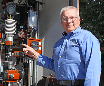 Senior Applications Engineer J. R. Madden has extensive experience with all things relating to temperature. In this recurring feature, he'll address common customer issues and Moore Industries' solutions.
Q: Do I need to order anything differently if I’m measuring cryogenic temperatures?
A: When measuring temperatures below -10°F, readings are more stable and accurate when a wire-wound RTD element is used. Typical thin-film RTD elements do not perform well at these extreme temperatures.
Q: What about measuring temperatures above 850°F with an RTD? Should I specify a thin-film or wire-wound RTD element?
A: When using RTDs to measure temperatures above 850°F, we recommend using a wire-wound RTD element that is specially built to handle these high temperatures. Many thin-film RTD elements will experience high failure rates at these temperatures.
If you require an RTD sensor for these temperature extremes, order a wire-wound (-WW option) element to ensure the best sensor performance and longevity.
Do you want more information? Download the data sheet. Or visit the catalog.
Need to get price or availability or have a technical question?
Send us a message using E-Help.
Q: I am installing 24 SPA RTD transducers (Model: SPA/RTD/2PRG/U/-AO [DIN]) and I have a question about how the 4-20mA is powered. They are currently wired as loop-powered and I would like to confirm that this model supports loop-powered field devices.
A: The SPA/TPRG/2PRG/U/-AO [DIN] supports both source and sink mode on its current analog output. The default setting for the AO (analog output) is 4-20mA with the loop voltage sourced from the SPA. Please see Figure 4 in the SPA installation manual for changing the AO (analog output) to Current Source/Sink or a Voltage output.
Do you want more information? Download the data sheet. Or visit the catalog.
Need to get price or availability or have a technical question?
Send us a message using E-Help.
Q: I need to order an FDY transmitter for monitoring up to 13600 Hz from a magnetic pickup on a gas turbine for speed indication. Do you recommend the PRG or 10-250V input option?
A: Either model is compatible with the frequency you mentioned. The PRG input is normally correct for magnetic pickups. Some will put out a pulse voltage above 30Vac (the maximum for the PRG input), but this can be lowered by moving the pickup farther from the target. Use the 10-250AC input if you are certain that the voltage pulse will be above the PRG’s upper limit. But with this model, the pulse must be at least 10Vac.
Please note that the 10-250Vac input is not available with I.S. approvals.
Model Examples:
FDY/PRG/4-20MA/12-42DC [HP]
FDY/10-250AC/4-20MA/12-42DC [HP]
Do you want more information? Download the data sheet. Or visit the catalog.
Need to get price or availability or have a technical question?
Send us a message using E-Help.
Q. We are looking for a signal isolator. We need an input of 0-5VDC, output 4-20mA and the unit needs to be output loop powered. What do you recommend?
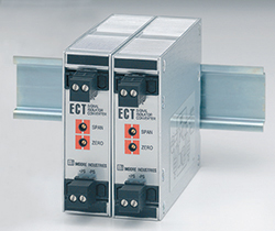
A. The ECT is available with an input 0-5VDC, you’ll need to specify when ordering. The ECT DIN-style signal isolator, converter, repeater, booster and splitter feature solid metal housings that stand up to continuous, daily rigors of process control and factory automation applications. The 2-wire, output-loop powered ECT operates on 12-42DC. A 4-wire, line powered model is also available if voltage outputs or large output drive capabilities are required.
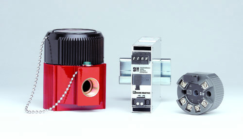
SIY DIN-style signal isolators can also perform the same function and they are PC configurable. The highly versatile SIY programs to accept a wide range of current or voltage inputs. It outputs an isolated, proportional, 4-20mA signal. This 2-wire (loop-powered) transmitter programs in seconds to handle a wide range of important signal interface applications. If field installation is required for your signal converter, the SIY is also available in a weatherproof or hazardous area enclosure. A configuration cable is required to utilize the PC programming capability of the SIY. Use either a Serial RS232 cable with 9 pin connector or USB cable made by Moore Industries.
Another DIN-style mount option is the MIX. The model MIX is also a 2-wire (loop powered) 2-channel or 4-channel isolator/converter. The 2-channel MIX provides conveniently-located DIP switches for selecting input types of 4-20mA, 0-5V, 1-5V or 0-10V for each channel.
Read more about the ECT, SIY and MIX.
Do you want more information? Download the data sheet. Or visit the catalog.
Need to get price or availability or have a technical question?
Send us a message using E-Help.
Q. I need to boost a 4-20mA signal to get a Fisher FIELDVIEW DVC6200 to respond to a control signal. What could I use?
Q. On a 4-20mA gas detector, while we replace the cell, the output reverts to 3mA. This causes the device receiving the 4-20mA signal to go into a critical alarm condition and can shut down a critical process. What device do you have that will keep the output at no less than 4mA?
It would also be convenient to have this instrument provide me with a 'relay alarm contact output' when my input goes to 3mA. It can be 24Vdc or 120Vac. It should be in a DIN housing.
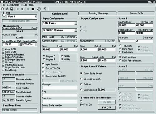
A. Moore Industries CPT PC-Programmable Temperature Transmitter and Signal Isolator/Converter CPT/HLPRG/0-20MA/117AC*/-C [DIN] can be used for this application. A configuration cable is required to utilize the PC programming capability. The selected model will have the functions of the signal repeater with an alarm relay output. You can set the alarm fault relay to trigger at your choice of input signal level below 4mA.
The CPT has a menu selection for upper and lower limits. You can set 3.9mA low limit there.
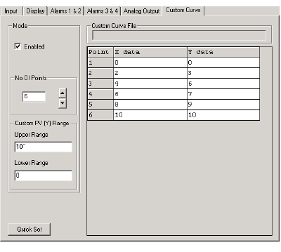
The SPA2 upper and lower limits must be defined by setting up a “custom curve” lookup table which (below), in this case, will be 5 points where in = out. By using the custom curve table, the output will not go below the lowest ordered pair or above the highest ordered pair. In this case it will define the lower output limit.
Do you want more information? Download the data sheet. Or visit the catalog.
Need to get price or availability or have a technical question?
Send us a message using E-Help.
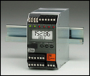
 The SIL3 capable SLD features a large integral display that shows real-time process status in mA, percent, or any designated 5-character Engineering units (EGU). The latest addition to the Moore Industries’ FS Functional Safety Series products, it is certified by exida® as a SIL3 capable, non-interfering device for use in a safety loop. The SLD is the perfect solution to accurately and reliably display process status in a safety loop, and features the Loop Maintenance Diode Option which allows it to be removed from the safety loop without affecting the integrity of the safety function. Find out more here.